
Object Oriented System Design
General Objectives
- Visualize the concept of object oriented technology in designing new or reengineering existing systems.
- Conceptualize the importance of UML, AUML, and other object-oriented tools for developing or reengineering complex systems.
Specific Objectives
- To make students realize the importance of object-oriented methods in modern software development.
- To clarify the various object-oriented tools and their applications.
- To familiarize students with techniques for developing new systems using object-oriented tools.
- To involve students in designing projects based on core object-oriented concepts, including AI integration and cloud-native approaches.
2026 Edition – MSc IT, Purbanchal University
- U1: Intro (5H) ·
- U2: OOD (10H) ·
- U3: UML (10H) ·
- U4: Domain (10H) ·
- U5: Agent UML (5H) ·
- U6: Metrics (5H) ·
- U7: OOSDLC (5H) ·
- U8: Project (10H) ·
- Exam
Unit 1: Introduction (5 Hrs)
General Concepts, Need of Object-Oriented Systems, Defining & Attributes of Complex Systems, OOA vs OOD – Foundation for Modern Software Engineering
In-depth Explanation
Object-Oriented System Design (OOSD) is a mature yet evolving methodology that structures software systems around real-world entities represented as objects. Each object combines data (attributes/state) and operations (methods/behavior) in a self-contained unit, promoting better organization, maintainability, and scalability compared to traditional procedural (function-centric) approaches.
This unit lays the conceptual groundwork for the entire course by addressing why object-oriented technology is indispensable in 2026, especially when engineering or reengineering complex systems. A complex system is not merely "complicated" — it is defined by many interdependent parts that interact in non-linear ways, producing emergent properties (whole-system behaviors that cannot be reduced to individual components).
Core Attributes of Complex Systems (with 2026 relevance):
- High interconnectivity & interdependence: A change in one element (e.g., a microservice failure) can cascade unpredictably.
- Non-linear interactions & feedback loops: Small inputs can cause disproportionate effects (amplifying or damping).
- Emergence: New patterns/behaviors arise at the system level (e.g., swarm intelligence in agent-based AI).
- Adaptability & resilience: Systems self-organize and recover from disruptions (critical for cloud-native apps under load).
- Scalability challenges & uncertainty: Handling dynamic environments (IoT growth, real-time AI inference, global user spikes).
Procedural programming struggles with these traits due to global state, tight coupling, and poor reusability. Object-oriented methods provide powerful tools to tame complexity through:
- Abstraction → Hide unnecessary details, focus on essential interfaces
- Encapsulation → Protect internal state, expose controlled access
- Modularity & Reusability → Classes and objects as reusable building blocks
- Hierarchy & Composition → Inheritance for "is-a" relationships, composition for "has-a" flexibility
2026 Modern Nuances & Trends (cutting-edge academic & industry perspective):
- AI Integration: Objects now model intelligent agents — reinforcement learning environments, neural network layers, or decision-making modules become first-class classes with autonomous behavior.
- Cloud-Native OOD: Microservices, serverless functions (AWS Lambda, Google Cloud Run), and Kubernetes pods are designed as independent, self-contained objects with loose coupling and high cohesion.
- Agent-Oriented Trends: Extension of OO toward proactive, goal-driven, socially capable agents in multi-agent systems (MAS) — e.g., autonomous supply chain agents, self-healing cloud infrastructures, or collaborative AI teams.
OOA vs OOD – Key Distinction:
Object-Oriented Analysis (OOA) is the problem space phase: understanding "what" the system must do, modeling real-world domain concepts, requirements, and use cases.
Object-Oriented Design (OOD) is the solution space phase: defining "how" to build it — concrete classes, interfaces, patterns, algorithms, and architecture.
Visual Representations
Below is a curated set of high-resolution diagrams from trusted educational sources to help you visualize complex systems, the OO paradigm shift, OOA vs OOD distinction, and modern AI/cloud/agent integrations.

Complex Systems: Attributes, Emergence & Feedback Loops
OOA vs OOD – Core Differences & Process Flow

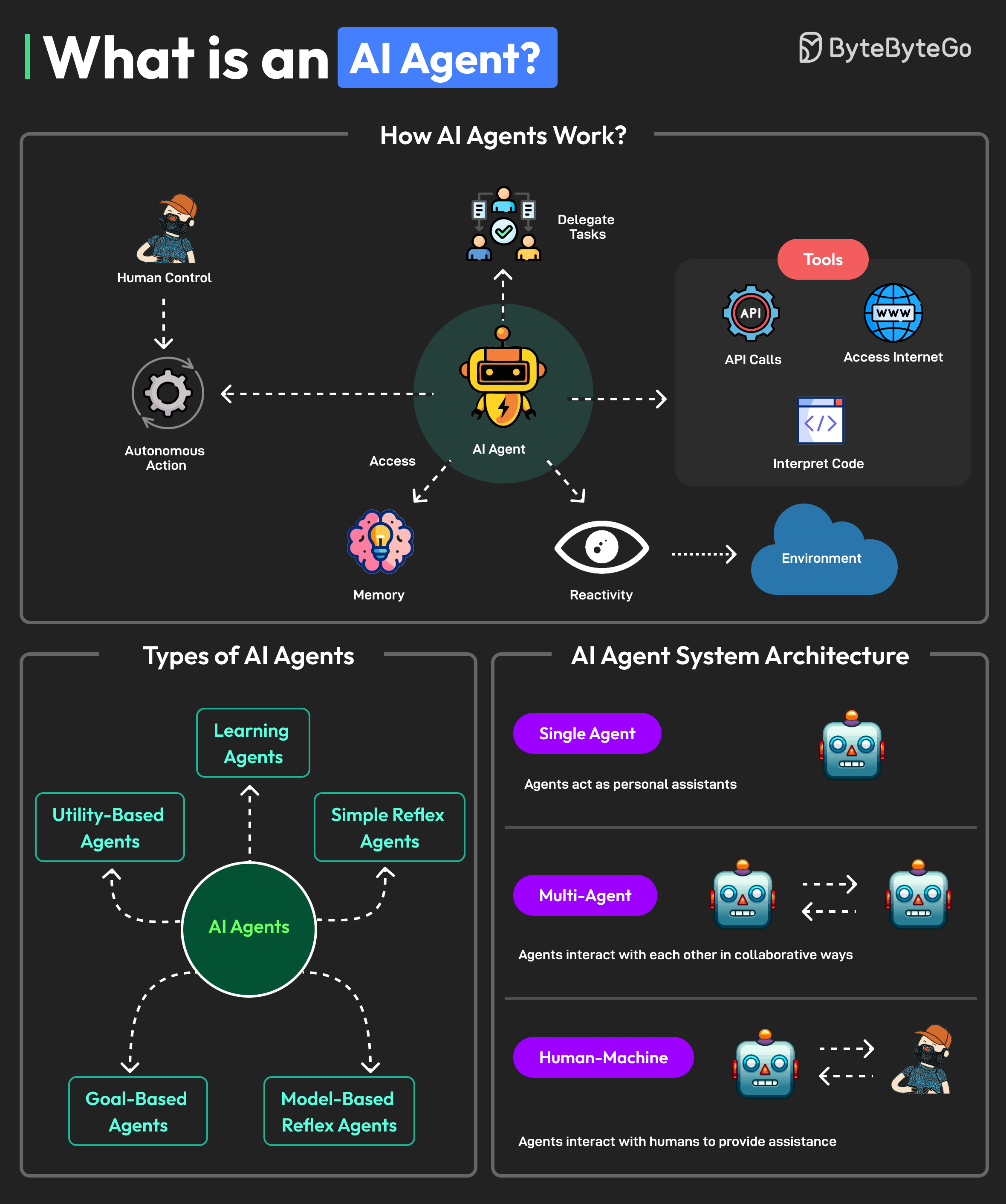
Trends: AI Agents, Cloud-Native Objects & Multi-Agent Systems
Recommended Video Resource
MIT OpenCourseWare – Timeless yet highly relevant introduction to OO concepts (perfect for building strong MSc-level foundations)
- U1: Intro (5H) ·
- U2: OOD (10H) ·
- U3: UML (10H) ·
- U4: Domain (10H) ·
- U5: Agent UML (5H) ·
- U6: Metrics (5H) ·
- U7: OOSDLC (5H) ·
- U8: Project (10H) ·
- Exam
Unit 2: Object Oriented Design (10 Hrs)
Defining OOD, General Characteristics, Benefits of Object Model, Core Concepts: Class, Object, Inheritance, Polymorphism, Encapsulation, Abstraction
In-depth Explanation
Object-Oriented Design (OOD) is the critical phase that transforms the abstract understanding from analysis into a concrete, implementable blueprint for software construction. It focuses on defining classes, objects, relationships, interfaces, and behaviors that will form the foundation of the system.
General Characteristics of Good OOD (2026 Perspective):
- High Cohesion – each class has a single, well-defined responsibility
- Low Coupling – minimal dependencies between classes
- Strong Encapsulation & Information Hiding
- Reusability through inheritance, composition, and interfaces
- Flexibility & Extensibility via polymorphism and design patterns
- Support for modern practices: microservices, serverless, DevOps pipelines, and AI-agent integration
Key Benefits of the Object Model:
- Natural mapping to real-world entities → easier understanding & maintenance
- Improved modularity → independent development & testing
- Better code reuse → reduces redundancy & bugs
- Easier evolution & refactoring → especially important in agile/DevOps environments
- Supports complex systems – handles emergence, scalability, and adaptability
Core Concepts – Detailed Breakdown:
- Class: Static blueprint/template defining attributes (data members) and methods (operations)
- Object: Runtime instance of a class with its own unique state (memory allocated at creation)
- Inheritance: "is-a" relationship – allows specialization (subclass extends superclass). Supports code reuse but must avoid deep hierarchies (favor composition)
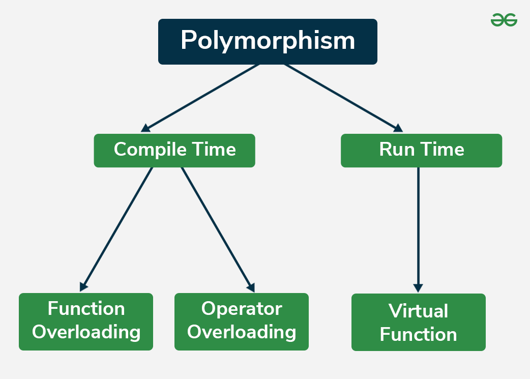
- Polymorphism: "Many forms" – allows objects of different classes to be treated uniformly (method overriding, interface implementation). Essential for flexible AI algorithm swapping, plugin systems, and cloud service abstractions
- Encapsulation: Bundling data and methods together; restricting direct access to internal state (private/protected access modifiers)
- Abstraction: Hiding complex implementation details, exposing only necessary interface (abstract classes, interfaces)
2026 Modern Relevance & Applications:
- Cloud-Native Design: Classes represent deployable units (microservices, functions-as-code). Loose coupling is critical for scalability & fault tolerance
- AI Integration: Polymorphism enables runtime swapping of ML models (CNN vs Transformer). Inheritance models agent hierarchies (BasicAgent → LearningAgent → AutonomousAgent)
- Agent-Oriented Extension: Objects become proactive agents with goals, beliefs, plans – used in multi-agent systems for autonomous decision-making
Visual Representations
High-resolution diagrams from trusted educational sources to help you deeply understand OOD concepts, relationships, and modern applications.
Class vs Object – Basic Relationship

Source: GeeksforGeeks
Inheritance Hierarchy (Vehicle → Car Example)

Source: GeeksforGeeks
Polymorphism – Method Overriding Example
Source: GeeksforGeeks
Encapsulation & Data Hiding

Source: TutorialsPoint
2026 Trends: Cloud-Native Microservices as Objects
Source: Medium – Modern OOD
Recommended Video Resource
Clear, exam-oriented walkthrough of all core OOD concepts with practical examples (highly recommended)
- U1: Intro (5H) ·
- U2: OOD (10H) ·
- U3: UML (10H) ·
- U4: Domain (10H) ·
- U5: Agent UML (5H) ·
- U6: Metrics (5H) ·
- U7: OOSDLC (5H) ·
- U8: Project (10H) ·
- Exam
Unit 3: UML (10 Hrs)
Definitions and Concepts, All Major UML Diagrams: Class & Object, Use Case, Sequence, State, Package, Activity, Component, Deployment
In-depth Explanation
Unified Modeling Language (UML) is the standardized visual modeling language for specifying, visualizing, constructing, and documenting software systems. It provides a common vocabulary for developers, architects, and stakeholders to communicate complex designs unambiguously.
Key Concepts in UML (2026 Context):
- Structural diagrams: Static aspects (what the system is composed of)
- Behavioral diagrams: Dynamic aspects (how the system behaves over time)
- Extensibility: Profiles, stereotypes, tagged values
- Integration with modern tools: Auto-generation via AI-assisted modeling, DevOps pipeline visualization, and Agent UML extensions for autonomous systems
Major UML Diagrams Covered:
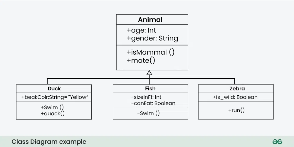
- Class & Object Diagram: Shows classes, attributes, operations, relationships (inheritance, association, aggregation, composition)
- Use Case Diagram: Captures functional requirements from actor perspective (actors, use cases, relationships: include, extend, generalization)
- Sequence Diagram: Interaction over time (lifelines, messages, activation bars, loops, alternatives)
- State Diagram (State Machine): Lifecycle of an object (states, transitions, events, guards, actions)
- Package Diagram: Organizes elements into namespaces (dependency management)
- Activity Diagram: Workflow/process modeling (actions, decisions, forks/joins, swimlanes)
- Component Diagram: Modular components and their interfaces/dependencies
- Deployment Diagram: Physical architecture (nodes, artifacts, communication paths)
2026 Modern Nuances: UML supports cloud-native (deployment for Kubernetes), AI (sequence for agent interactions), and DevOps (activity for CI/CD pipelines). Extensions like AUML add agent-specific notations (protocols, roles).
Visual Representations
High-resolution UML diagrams from trusted sources to master each type visually.
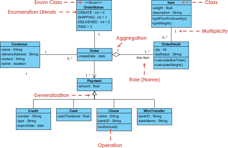
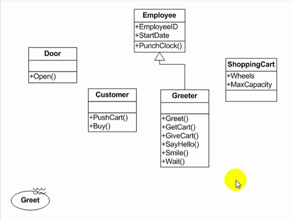
UML Class Diagram (with Inheritance & Associations)
Source: GeeksforGeeks
UML Use Case Diagram – Online Shopping Example
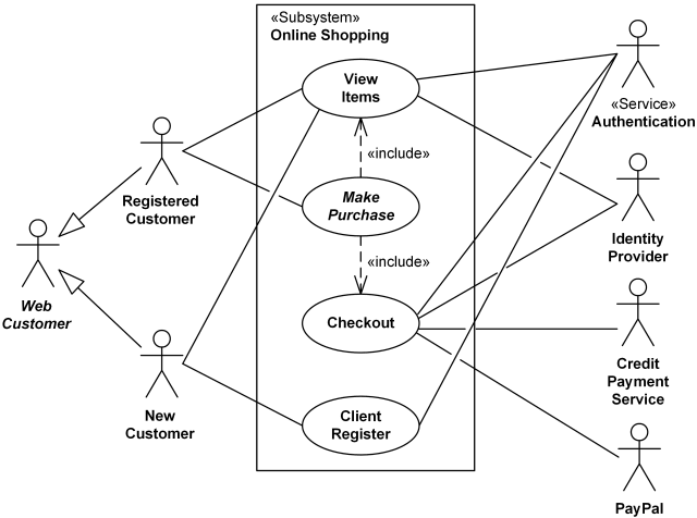
Source: UML-diagrams.org
UML Sequence Diagram – Object Interactions

Source: Visual Paradigm
UML State Machine Diagram Example
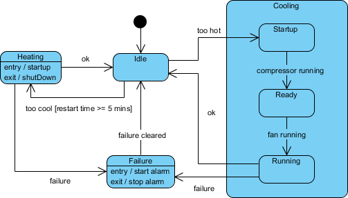
Source: Visual Paradigm
UML Activity Diagram – Order Processing
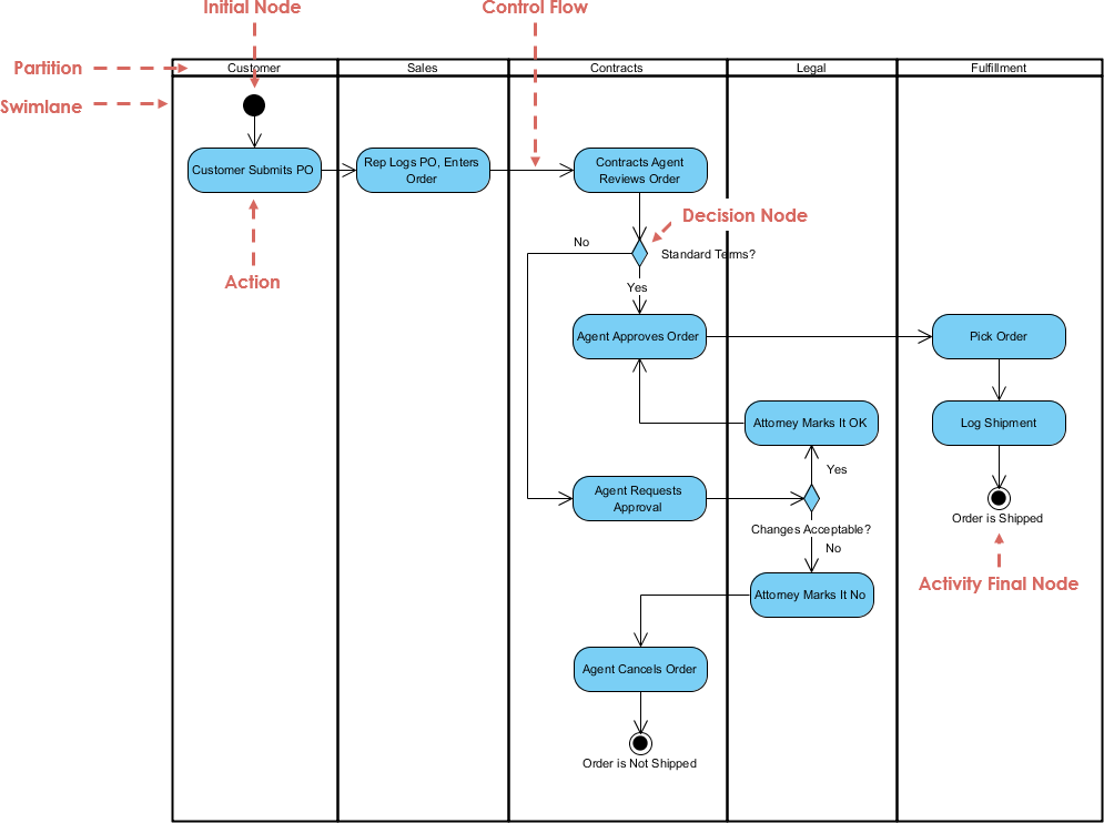
Source: Visual Paradigm
UML Component & Deployment Diagrams
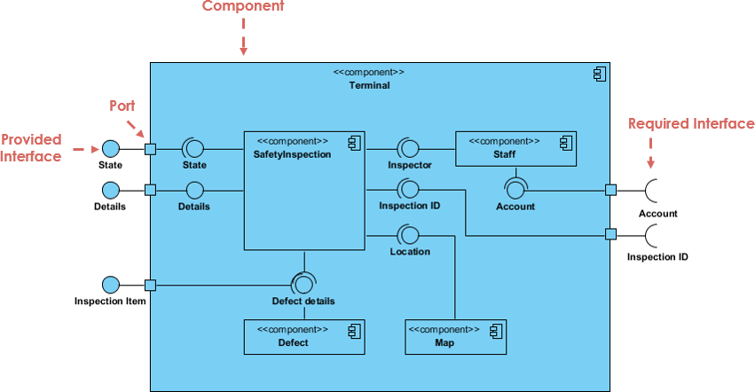
Source: Visual Paradigm
Recommended Video Resource
Comprehensive UML overview covering all diagram types (ideal for exam preparation)
- U1: Intro (5H) ·
- U2: OOD (10H) ·
- U3: UML (10H) ·
- U4: Domain (10H) ·
- U5: Agent UML (5H) ·
- U6: Metrics (5H) ·
- U7: OOSDLC (5H) ·
- U8: Project (10H) ·
- Exam
Unit 4: Domain Analysis (10 Hrs)
Concepts & Definition, Domain Class Model, Finding Classes/Associations/Methods/Attributes, Refining with Inheritance, Data Dictionary, Access Paths, Iteration, Packaging, Application Analysis
In-depth Explanation
Domain Analysis is the systematic process of identifying, modeling, and documenting the core concepts, entities, and rules of the problem domain to create a reusable, high-quality foundation for system development.
Key Steps in Domain Analysis (iterative & incremental):
- Finding Classes: Identify nouns in requirements as candidate classes (tangible/intangible concepts)
- Associations: Discover relationships between classes (multiplicity, direction, roles)
- Finding Attributes & Methods: Assign properties/behaviors; use CRC cards or brainstorming
- Data Dictionary: Precise definitions for all terms/classes/attributes
- Refining with Inheritance: Generalize/specialize (avoid overuse)
- Testing Access Paths: Ensure navigability (no dangling references)
- Iteration: Refine model through reviews & feedback
- Grouping into Packages: Logical organization for large domains
- Application Analysis: Bridge domain model to specific system requirements
2026 Modern Nuances: AI-assisted class discovery (NLP on requirements), cloud-native domain models (microservice boundaries), agent-oriented refinements (autonomous domain entities).
Visual Representations
Clear domain model examples and class identification diagrams.
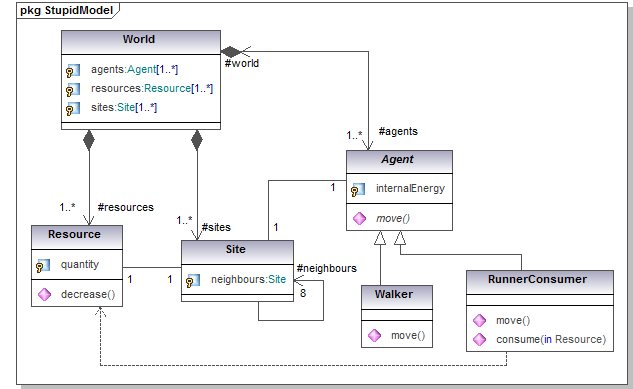
Domain Class Model Example (Hospital System)
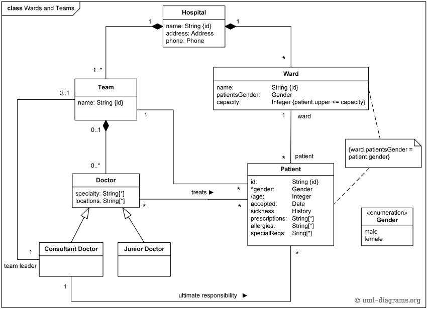
Source: UML-diagrams.org
Identifying Classes, Associations & Attributes in Domain Analysis
Source: Visual Paradigm
Classic Domain Model Structure

Source: Wikipedia
Recommended Video Resource
Step-by-step domain analysis and class modeling tutorial (excellent for understanding the process)
- U1: Intro (5H) ·
- U2: OOD (10H) ·
- U3: UML (10H) ·
- U4: Domain (10H) ·
- U5: Agent UML (5H) ·
- U6: Metrics (5H) ·
- U7: OOSDLC (5H) ·
- U8: Project (10H) ·
- Exam
Unit 5: Agent UML (5 Hrs)
Defining Agents, Agent Orientation, Agent-Oriented Programming, Common Features of Agents and Representation in AUML
In-depth Explanation
Agent UML (AUML) is an extension of standard UML specifically designed for modeling agent-oriented systems. It supports the representation of autonomous, intelligent, proactive entities (agents) that differ from traditional objects by having goals, beliefs, plans, and social capabilities.
Defining Agents:
- Autonomous entities that perceive their environment and act upon it to achieve goals
- Key properties: Autonomy (independent decision-making), Reactivity (response to changes), Proactivity (goal-directed behavior), Social ability (interaction/communication with other agents)
- Types: Reactive agents (simple rule-based), Cognitive agents (belief-desire-intention – BDI), Hybrid agents
Agent Orientation: Shifts focus from passive objects to active agents capable of initiative, negotiation, and adaptation – essential for modern complex systems like multi-agent systems (MAS), IoT, swarm robotics, and autonomous AI.
Agent-Oriented Programming (AOP): Paradigm where programs are built using agents as first-class entities (e.g., JADE, Jason, SPADE frameworks). Agents communicate via ACL (Agent Communication Language), have internal states, and execute plans.
Common Features & AUML Representation:
- Roles, capabilities, protocols (extended sequence diagrams with lifelines for agents)
- Agent interaction diagrams, role models, commitment protocols
- Belief, Desire, Intention (BDI) structures in class-like notations
- Extensions: Agent stereotypes, tagged values for mental states (beliefs, goals, plans)
2026 Relevance: Critical for AI agents in cloud-native ecosystems (e.g., self-organizing multi-agent DevOps, autonomous microservices, collaborative AI in edge computing).
Visual Representations
High-resolution diagrams showing Agent UML notations, multi-agent architectures, and BDI models.
Agent UML – Class Diagram with Roles & Capabilities

Source: ResearchGate – Agent UML Example
Multi-Agent System Architecture (AUML Hierarchy)

Source: ResearchGate – Agent Types Hierarchy
AUML Interaction Diagram for Agent Communication

Source: ResearchGate – Multi-Agent UML
Recommended Video Resource
Clear explanation of Agent UML and its differences from standard UML (great for MSc depth)
- U1: Intro (5H) ·
- U2: OOD (10H) ·
- U3: UML (10H) ·
- U4: Domain (10H) ·
- U5: Agent UML (5H) ·
- U6: Metrics (5H) ·
- U7: OOSDLC (5H) ·
- U8: Project (10H) ·
- Exam
Unit 6: Object Oriented Metrics (5 Hrs)
Internal Quality of Design, Principles of Object Oriented Design, Software Quality, Metrics for Object Oriented Systems (CK, MOOD)
In-depth Explanation
Object-Oriented Metrics quantify internal design quality to guide refactoring, predict maintainability, and ensure adherence to OO principles (high cohesion, low coupling, reuse).
Software Quality in OO Context: Focuses on maintainability, reusability, efficiency, testability, and extensibility – measured via structural metrics.
Key Principles of OO Design: SOLID (Single Responsibility, Open-Closed, Liskov Substitution, Interface Segregation, Dependency Inversion), high cohesion, low coupling.
Major Metrics Suites:
- CK Metrics (Chidamber & Kemerer, 1994 – most widely used):
- WMC: Weighted Methods per Class (complexity)
- DIT: Depth of Inheritance Tree
- NOC: Number of Children
- CBO: Coupling Between Objects
- RFC: Response For a Class
- LCOM: Lack of Cohesion in Methods
- MOOD Metrics (Abreu, 1995 – quality factors):
- MHF/AHF: Method/Attribute Hiding Factor
- MIF/AIF: Method/Attribute Inheritance Factor
- PF: Polymorphism Factor
- CF: Coupling Factor
2026 Usage: Integrated into CI/CD pipelines (SonarQube, CodeClimate), applied to cloud-native and AI designs (e.g., low CBO for microservices, high PF for polymorphic AI models).
Visual Representations
Diagrams of CK and MOOD metrics hierarchies and explanations.
CK Metrics Suite Overview
Source: ResearchGate – OO Metrics Hierarchy
MOOD Metrics – Quality Factors

Source: ResearchGate – MOOD Metrics
Object-Oriented Metrics Comparison (CK vs MOOD)

Source: ResearchGate – Metrics Comparison
Recommended Video Resource
Detailed walkthrough of CK & MOOD metrics with examples (perfect for quality assessment in exams)
- U1: Intro (5H) ·
- U2: OOD (10H) ·
- U3: UML (10H) ·
- U4: Domain (10H) ·
- U5: Agent UML (5H) ·
- U6: Metrics (5H) ·
- U7: OOSDLC (5H) ·
- U8: Project (10H) ·
- Exam
Unit 7: Object Oriented System Development Life Cycle (5 Hrs)
S/W Development Process, Building High Quality Software, Approaches to System Testing, Verification & Validation, OO Approach for S/W Development, Prototyping
In-depth Explanation
The Object-Oriented System Development Life Cycle (OO SDLC) adapts traditional software development phases to the OO paradigm, emphasizing iteration, reusability, and incremental delivery.
Key Phases in OO SDLC:
- Planning & Requirements (OOA focus)
- Analysis & Domain Modeling
- Design (OOD: classes, patterns, architecture)
- Implementation (coding with OO languages)
- Testing & Integration (unit, integration, system testing)
- Deployment & Maintenance (iterative enhancements)
Building High-Quality Software: Emphasizes verification (build right product) & validation (right product), defect prevention through early modeling, design reviews, and metrics.
Approaches to Testing: Unit testing (classes/objects), integration (interactions), system testing (use cases), regression testing (after changes).
OO-Specific Advantages: Easier testing due to encapsulation, polymorphism for mock objects, reusability reduces defects.
Prototyping: Rapid OO prototypes (e.g., UI with classes) for user feedback, iterative refinement.
2026 Trends: Agile/DevOps integration, AI-automated testing, cloud-native CI/CD pipelines, continuous validation in agent-oriented systems.
Visual Representations
Diagrams illustrating OO SDLC phases, testing approaches, prototyping, and modern DevOps integration.
Object-Oriented SDLC Phases & Iteration

Source: https://www.geeksforgeeks.org/system-design-life-cycle-sdlc/
V-Model Adapted for OO Development
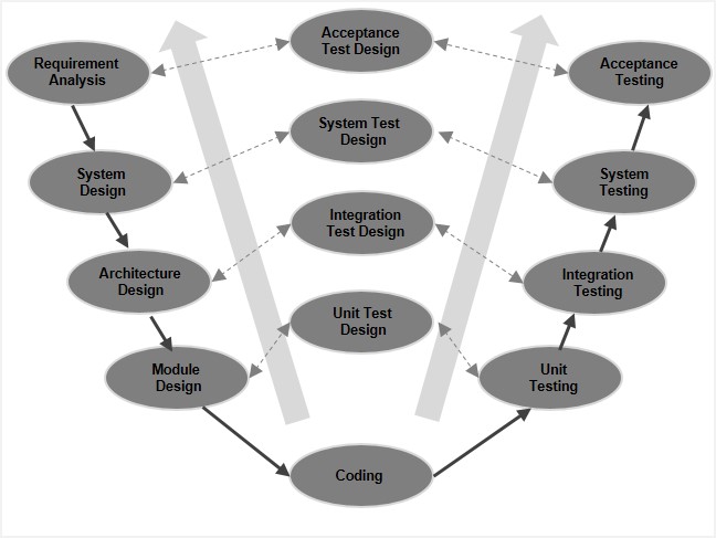
Source: https://www.tutorialspoint.com/sdlc/sdlc_v_model.htm
Prototyping Process in OO SDLC

Source: https://miro.medium.com/
Testing Levels in OO Systems
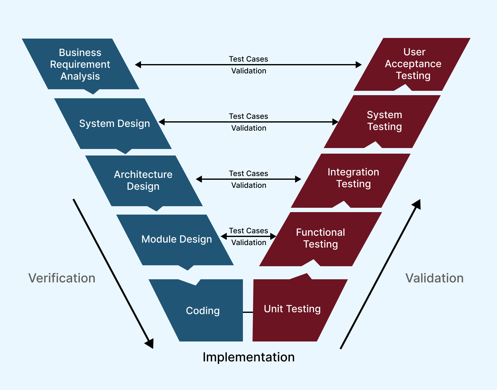
Source: https://www.lambdatest.com/blog/v-model/
Recommended Video Resource
Detailed explanation of OO SDLC with practical examples (highly recommended for exams)
- U1: Intro (5H) ·
- U2: OOD (10H) ·
- U3: UML (10H) ·
- U4: Domain (10H) ·
- U5: Agent UML (5H) ·
- U6: Metrics (5H) ·
- U7: OOSDLC (5H) ·
- U8: Project (10H) ·
- Exam
Unit 8: Project Design (10 Hrs)
Detailed Project Design using OO Concepts, UML, Domain Analysis, Metrics, SDLC, AUML – Capstone Application
In-depth Explanation
This unit integrates all previous concepts into a **comprehensive project design**. Students apply OOA/OOD, UML diagrams, domain analysis, metrics evaluation, OO SDLC, and AUML to design a complete system.
Typical Project Steps:
- Requirements gathering & domain analysis
- Build domain class model (classes, associations, inheritance)
- Apply UML diagrams (use case, class, sequence, state, etc.)
- Refine design with patterns, metrics (CK/MOOD for quality)
- Plan OO SDLC phases (iterative prototyping, testing)
- Use AUML for agent-based features (if applicable)
- Document architecture, deployment, and quality assurance
2026 Recommended Project Ideas: AI-enhanced e-learning platform, cloud-native hospital management system, autonomous multi-agent supply chain, smart retail with recommendation agents.
Focus on real-world applicability: cloud-native deployment, AI integration, DevOps, and measurable quality.
Visual Representations
Complete project design examples, full UML sets, and architecture diagrams.
Complete UML Diagrams for a Sample Project
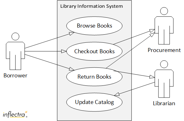
Source: https://www.inflectra.com/
OO Project: E-commerce System Class Diagram

Source: ResearchGate
Project Communication Diagram
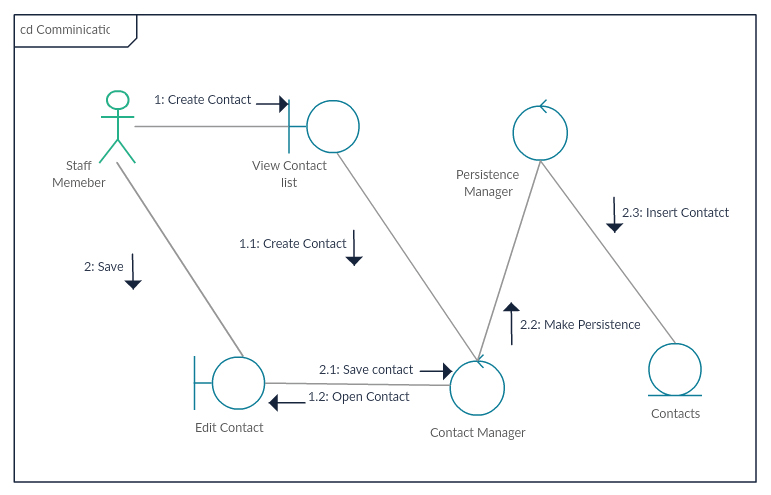
Source: https://d3n817fwly711g.cloudfront.net/
2026 Cloud-Native OO Project Architecture

Source: https://www.canva.com/
Recommended Video Resource
End-to-end project design walkthrough using UML & OO concepts (perfect capstone reference)
- U1: Intro (5H) ·
- U2: OOD (10H) ·
- U3: UML (10H) ·
- U4: Domain (10H) ·
- U5: Agent UML (5H) ·
- U6: Metrics (5H) ·
- U7: OOSDLC (5H) ·
- U8: Project (10H) ·
- Exam
Exam Questions & Model Solutions – Purbanchal University MSc IT
Object Oriented System Design (2023 Pattern – Full Marks Oriented Answers)
These model answers are written in complete exam format (introduction → main points → examples → diagrams → conclusion). Students can score full marks by writing similarly structured answers.
1. Why are software systems complex? Explain the properties of complex systems.
Software systems are considered complex due to their large size, numerous interacting components, dynamic requirements, and unpredictable behavior. Complexity arises from both technical and human factors such as changing user needs, integration with legacy systems, scalability demands, and emergent properties.
Key Properties of Complex Systems:
- High Interconnectivity & Interdependence
Components are tightly linked; a small change in one part (e.g., a microservice update) can affect the entire system (cascading failures). - Non-linearity & Feedback Loops
Small inputs produce disproportionately large outputs (positive feedback amplifies issues, negative feedback stabilizes). - Emergence
System-level behaviors arise that cannot be predicted from individual parts (e.g., swarm intelligence in multi-agent systems). - Adaptability & Resilience
Systems can self-organize and recover from disturbances (cloud-native systems auto-scale under load). - Scalability Challenges & Uncertainty
Difficult to handle exponential growth (users, data, traffic) with uncertain future requirements (IoT, real-time AI).
Conclusion: Due to these properties, traditional structured approaches fail. Object-oriented methods, modular design, iterative development, and modern tools (UML, metrics, agent orientation) are essential to manage complexity effectively.
2. Explain class hierarchy with examples. How do we identify classes while designing a software system? Explain.
Class Hierarchy is the organized structure of classes based on inheritance, forming a tree-like (or lattice) arrangement where subclasses inherit attributes and methods from superclasses.
Example:
Superclass: Vehicle (attributes: speed, color; methods: start(), stop())
Subclasses: Car (adds: numDoors), Bike (adds: engineCC), Truck (adds: loadCapacity)
→ Car, Bike, Truck inherit start() and stop() → promotes reusability.
How to Identify Classes (Techniques):
- Noun Phrase Technique: Scan requirements document; nouns/noun phrases are potential classes (e.g., "Student", "Book", "Librarian").
- CRC Cards (Class-Responsibility-Collaboration): Brainstorm each class's responsibilities and collaborators (who it works with).
- Domain Knowledge & Use Case Analysis: Identify real-world entities from domain experts and use case actors.
- Elimination Rules: Discard external entities, attributes-only items, or actions as classes.
- Modern Approach (2026): Use AI/NLP tools to extract classes from requirements automatically.
Conclusion: Proper class identification and well-designed hierarchy reduce redundancy, improve maintainability, and support extensibility. Prefer composition over deep inheritance.
3. What are UML diagrams? Explain the importance of UML in the OO system.
UML (Unified Modeling Language) is a standardized, graphical modeling language developed by OMG for visualizing, specifying, constructing, and documenting object-oriented systems.
Importance of UML in OO Systems:
- Standardized Communication: Provides a common visual language for developers, designers, stakeholders, and clients — reduces miscommunication.
- Supports Full OO Lifecycle: From analysis (use case) → design (class/sequence) → implementation (component/deployment) → maintenance.
- Visualization of Complexity: Clearly represents static (class, package) and dynamic (sequence, activity) aspects of complex systems.
- Facilitates Design Quality: Helps apply patterns, detect flaws early, and perform reverse engineering.
- Tool Support & Automation: Many tools (Enterprise Architect, Lucidchart) generate code from UML; integrates with DevOps, AI-assisted modeling (2026).
- Extensibility: Supports profiles and extensions (e.g., AUML for agents).
Conclusion: UML is the de-facto standard in OO development, improving quality, productivity, and maintainability of software systems.
4. What are the techniques for developing new systems using the various object oriented tools.
Developing new systems using object-oriented tools involves a systematic approach combining analysis, design, modeling, and iterative implementation.
Major Techniques:
- Object-Oriented Analysis (OOA): Identify requirements, actors, use cases, domain entities (nouns), and build domain model.
- Object-Oriented Design (OOD): Define classes, relationships, apply design patterns (Singleton, Factory, Observer), create detailed UML diagrams.
- UML Modeling: Use case diagram → class → sequence → state → activity → component → deployment diagrams for complete visualization.
- Domain Analysis: Create reusable domain class models (classes, associations, inheritance).
- Prototyping: Develop rapid OO prototypes (throw-away or evolutionary) for requirements validation.
- Iterative & Incremental Development: Use agile/Scrum with continuous refactoring, testing, and feedback.
- Metrics Evaluation: Apply CK/MOOD metrics to ensure high cohesion, low coupling, and quality.
- Agent UML (AUML): Use for intelligent agent-based systems (roles, protocols, BDI structures).
Conclusion: These OO tools ensure modularity, reusability, maintainability, and alignment with modern paradigms like cloud-native and AI-integrated systems.
5 6. What is a domain class model? Explain domain analysis activities.
Domain Class Model is a conceptual, implementation-independent model that captures the key entities, relationships, attributes, and constraints of the real-world problem domain.
Domain Analysis Activities (Step-by-step):
- Identify Candidate Classes: Find nouns/noun phrases in requirements (e.g., Patient, Doctor, Appointment).
- Find Associations: Identify relationships between classes (e.g., Patient has-many Appointments) with multiplicity (1..*, 0..1).
- Identify Attributes & Methods: Assign properties (e.g., Patient: name, age) and behaviors (e.g., makeAppointment()).
- Prepare Data Dictionary: Define precise meaning of each term/class/attribute for consistency.
- Refine with Inheritance & Composition: Generalize/specialize (Person → Patient, Doctor); use composition for "has-a" relationships.
- Test Access Paths: Ensure navigability (can traverse from any class to others without dangling references).
- Iterate & Validate: Review with domain experts, refine repeatedly.
- Group into Packages: Organize large models into logical namespaces.
Conclusion: Domain class model provides a reusable foundation for application-specific design, reducing rework and improving quality.
7. What do agents in UML mean? Compare agent oriented and object oriented programming.
In UML, agents (modeled through Agent UML – AUML extension) are autonomous, intelligent, proactive software entities capable of perceiving their environment, making decisions, and acting to achieve goals.
Comparison: Agent-Oriented Programming (AOP) vs Object-Oriented Programming (OOP)
| Aspect | Object-Oriented Programming (OOP) | Agent-Oriented Programming (AOP) |
|---|---|---|
| Nature of Entity | Passive objects (react to method calls) | Active & autonomous agents (initiate actions) |
| Behavior Control | Deterministic methods | Goal-directed, reasoning, plans (BDI model) |
| Interaction Style | Synchronous/asynchronous method calls | Negotiation, protocols, ACL (Agent Communication Language) |
| State Representation | Attributes/data members | Beliefs, Desires, Intentions (mental states) |
| Typical Applications | General-purpose software, GUIs, enterprise apps | AI, multi-agent systems, robotics, IoT, autonomous systems |
| Modeling Tool | Standard UML | AUML (extended UML with agent roles, protocols) |
Conclusion: AOP extends OOP to handle intelligent, distributed, and adaptive systems in 2026 AI-driven environments.
8. Explain process, project and product metrics.
Software metrics are quantitative measures used to evaluate different aspects of software development.
1. Process Metrics
Measure the effectiveness and efficiency of the development process itself.
Examples: Defect density (defects per KLOC), productivity (LOC/person-month), cycle time, rework effort.
2. Project Metrics
Track project management performance.
Examples: Cost variance, schedule variance, effort estimation accuracy, team velocity (agile), resource utilization.
3. Product Metrics
Evaluate the quality of the final software product.
Examples: Size (LOC, function points), complexity (cyclomatic), maintainability (CK metrics: WMC, LCOM), reusability (MOOD: PF), reliability (MTBF).
Conclusion: In OO systems, product metrics (CK, MOOD) are most important for design quality, while process and project metrics support agile/DevOps delivery.
9. Explain object oriented system development process. Compare throw away and evolutionary prototyping.
Object Oriented System Development Process:
Iterative, incremental approach consisting of:
- Planning & Requirements Gathering
- Object-Oriented Analysis (OOA): Domain modeling, use cases
- Object-Oriented Design (OOD): Class design, patterns, UML
- Implementation: Coding with OO languages
- Testing: Unit, integration, system
- Deployment & Maintenance: Iterative enhancements
Comparison: Throw-away vs Evolutionary Prototyping
| Aspect | Throw-away Prototyping | Evolutionary Prototyping |
|---|---|---|
| Purpose | Explore & clarify requirements | Develop working system incrementally |
| Prototype Fate | Discarded after validation | Retained & evolved into final product |
| Risk | Low (not production code) | Higher (poor initial design may persist) |
| Time & Cost | Fast & low cost | Longer but delivers early value |
| Best For | UI validation, uncertain requirements | Complex systems needing continuous refinement |
| OO Suitability | Good for quick use case demos | Ideal for iterative OO development |
Conclusion: Evolutionary prototyping is preferred in modern OO agile processes.
10. Define verification and validation. Draw a state transition diagram for an ATM machine.
Verification: "Are we building the product right?"
Ensures that the system is built according to specifications (reviews, inspections, static analysis).
Validation: "Are we building the right product?"
Ensures the product meets user needs and expectations (user acceptance testing, beta testing).
State Transition Diagram for ATM Machine (Describe to Draw):
States: Idle → Card Inserted → PIN Verification → Transaction Menu → Processing → Dispense Cash / Print Receipt → Card Ejected → Idle
Transitions:
- Insert Card → Card Inserted
- Enter PIN (valid) → Transaction Menu
- Enter PIN (invalid) → Error → Card Ejected
- Select Withdrawal → Processing → Dispense Cash → Print Receipt → Card Ejected
- Cancel at any point → Return to Idle/Card Ejected
(In exam: Draw a clear state machine diagram with rounded rectangles for states, arrows for transitions, and labels for events/guards.)
11. Develop use case diagram, class diagram and sequence diagram for a library Management system.
1. Use Case Diagram
Actors: Member, Librarian, Admin
Use Cases:
- Member: Search Book, Borrow Book, Return Book, Pay Fine
- Librarian: Issue Book, Receive Return, Generate Report
- Admin: Add Book, Remove Book, Manage Member
Relationships: Include (Borrow includes Search), Extend (Return may extend Pay Fine)
2. Class Diagram
Main Classes:
- Book (ISBN, Title, Author, Status, Copies)
- Member (ID, Name, Contact, MaxBooks, Fine)
- Transaction (IssueDate, DueDate, ReturnDate, FineAmount)
- Librarian (ID, Name)
Relationships:
- Member borrows Book (association, multiplicity 1..* to 0..*)
- Transaction links Member and Book
- Librarian manages Transaction
3. Sequence Diagram (Borrow Book Use Case)
Participants: Member, LibrarySystem, Librarian, Database
Flow:
1. Member → LibrarySystem: searchBook(title)
2. LibrarySystem → Database: checkAvailability()
3. Database → LibrarySystem: available
4. Member → LibrarySystem: requestBorrow(bookID)
5. LibrarySystem → Librarian: verifyMember(memberID)
6. Librarian → LibrarySystem: approved
7. LibrarySystem → Database: issueBook(bookID, memberID, issueDate)
8. Database → LibrarySystem: success
9. LibrarySystem → Member: bookIssued
(In exam: Draw all three diagrams neatly with proper UML notation – stick figures for actors, ovals for use cases, rectangles for classes, lifelines/messages for sequence.)
Exam Questions & Model Solutions – Purbanchal University MSc IT
Object Oriented System Design – Model Set Two (Full Marks Oriented)
Answers are structured for full marks: definition → explanation → examples → diagrams → conclusion. Infographic & diagram links are provided for better understanding/visual reference.
1. Define a complex system. Explain the attributes of complex systems.
Definition: A complex system is a system composed of many interconnected and interdependent parts that interact in non-linear ways, producing emergent behaviors that cannot be fully predicted or reduced to the properties of individual components.
Key Attributes of Complex Systems:
- Interconnectivity & Interdependence: Components are linked; change in one affects many others (e.g., microservice failure in cloud system).
- Non-linearity & Feedback Loops: Small changes cause large effects (positive feedback amplifies problems, negative stabilizes).
- Emergence: Whole-system behavior appears unexpectedly (e.g., traffic jams from simple car rules).
- Adaptability & Resilience: Ability to self-organize and recover (e.g., cloud auto-scaling).
- Scalability Challenges & Uncertainty: Difficult to predict behavior under growth or change (e.g., IoT networks).
Visual Reference (Infographic):
Complex Systems Attributes Infographic (ResearchGate)
Wikipedia Complex Systems Diagram
Conclusion: These attributes make traditional linear methods ineffective. OO, modular design, and iterative approaches are required to manage complexity.
2. Explain the features of object-oriented systems with example.
Object-oriented systems are built around objects that combine data and behavior, providing several powerful features.
Major Features with Examples:
- Encapsulation: Bundles data and methods; hides internal details.
Example: BankAccount class (private balance + deposit()/withdraw() methods). - Abstraction: Hides complexity, shows only essential interface.
Example: User sees drive() method of Car, not internal engine details. - Inheritance: Allows reuse through "is-a" relationship.
Example: Car, Bike inherit from Vehicle (start(), stop() methods reused). - Polymorphism: Same interface, different implementations.
Example: draw() method in Shape → Circle.draw() draws circle, Rectangle.draw() draws rectangle. - Modularity & Reusability: Classes as independent, reusable units.
Example: Logger class used across multiple modules.
Visual Reference:
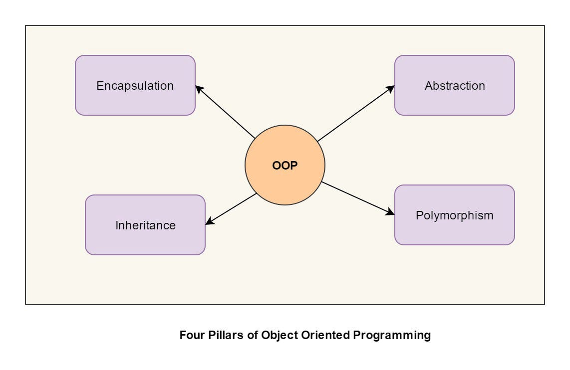
OOP Features Diagram (GeeksforGeeks)
Conclusion: These features improve maintainability, scalability, and real-world modeling in complex software systems.
3. Explain cardinality with example. Compare associations, compositions and aggregations with example.
Cardinality (also called multiplicity) specifies the number of instances of one class that can/must be associated with instances of another class.
Examples of Cardinality:
- 1..1 (exactly one)
- 0..1 (zero or one)
- 1..* (one or many)
- *..* (many to many)
Comparison: Association, Aggregation, Composition
| Aspect | Association | Aggregation | Composition |
|---|---|---|---|
| Relationship Type | General link between classes | "Has-a" (whole-part, weak) | "Has-a" (whole-part, strong) |
| Ownership | No ownership | Part can exist independently | Part cannot exist without whole |
| Lifetime | Independent | Part survives whole | Part dies with whole |
| Notation | Solid line | Hollow diamond on whole | Filled diamond on whole |
| Example | Student attends University | Car has Wheel (wheel can exist separately) | House has Room (room cannot exist without house) |
Visual Reference:
Association, Aggregation & Composition Diagram (GeeksforGeeks)
Conclusion: Correct use ensures accurate real-world modeling and proper memory management.
4. Explain flow oriented domain modeling with the help of a data flow diagram.
Flow-Oriented Domain Modeling focuses on how data moves through the system, identifying processes, data stores, external entities, and data flows.
Data Flow Diagram (DFD) is the primary tool — graphical representation of data movement without timing/sequence details.
Components of DFD:
- External Entity: Source/sink of data (e.g., Customer)
- Process: Transforms data (e.g., Validate Order)
- Data Store: Stores data (e.g., Database)
- Data Flow: Arrows showing data movement
- External Entities: Customer, Payment Gateway
- Central Process: Online Shopping System
- Data Flows: Order Request, Payment Info, Confirmation
Visual Reference (Infographic):
Data Flow Diagram Example (TutorialsPoint)
Context Level DFD (Visual Paradigm)
Conclusion: DFD is useful in early analysis to understand data movement before switching to OO class modeling.
5. Explain state transition diagram with example
State Transition Diagram (State Machine Diagram) shows the lifecycle of an object — its states, transitions between states, events that cause transitions, and actions performed.
Key Elements:
- State: Rounded rectangle (e.g., Idle, Active)
- Transition: Arrow with event [guard]/action
- Initial State: Filled circle
- Final State: Circle with outer ring
States: Idle, Card Inserted, PIN Entered, Transaction Selected, Processing, Dispensing, Receipt Printed
Transitions:
- Insert Card → Card Inserted
- Enter Correct PIN → Transaction Selected
- Enter Wrong PIN → Error Message → Idle
- Select Withdrawal → Processing → Dispense Cash → Receipt Printed → Idle
Visual Reference:
ATM State Machine Diagram (UML-diagrams.org)
State Diagram Example (Visual Paradigm)
Conclusion: State diagrams help model object behavior over time, ensuring correct lifecycle handling.
6. What are agents in AUML? Compare AOP and OOP
Agents in AUML: In Agent UML (AUML – extension of UML), agents are autonomous, intelligent, proactive entities with goals, beliefs, plans, and social interaction capabilities. They are represented using special stereotypes, role models, interaction protocols, and BDI (Belief-Desire-Intention) structures.
Comparison: Agent-Oriented Programming (AOP) vs Object-Oriented Programming (OOP)
| Aspect | Object-Oriented Programming (OOP) | Agent-Oriented Programming (AOP) |
|---|---|---|
| Entity Type | Passive objects | Active & autonomous agents |
| Behavior | Method calls | Goal-directed, reasoning, plans |
| Interaction | Message passing | Negotiation, ACL protocols |
| Internal Structure | Attributes + methods | Beliefs, Desires, Intentions (BDI) |
| Primary Use | General software | AI, multi-agent systems, robotics |
Conclusion: AOP builds on OOP to handle intelligent, adaptive systems in 2026 (e.g., AI agents, IoT).
7. Design a class for issuing books in a library management system.
Class Name: BookIssue (or Transaction)
Attributes:
- issueID: String (primary key)
- bookISBN: String
- memberID: String
- issueDate: Date
- dueDate: Date
- returnDate: Date (null if not returned)
- fineAmount: double
- status: String (Issued, Returned, Overdue)
- issueBook(memberID, bookISBN): void
- calculateDueDate(): Date
- calculateFine(): double
- returnBook(returnDate): void
- isOverdue(): boolean
Relationships:
- Association with Member (1 Member → many Issues)
- Association with Book (1 Book → many Issues)
Conclusion: This class encapsulates the issuing process, supports fine calculation, and integrates with Member and Book classes.
8. Define software Quality. Compare black box and white box strategies for software testing.
Software Quality is the degree to which software meets stated and implied needs — includes functionality, reliability, usability, efficiency, maintainability, portability (ISO/IEC 25010).
Comparison: Black Box vs White Box Testing
| Aspect | Black Box Testing | White Box Testing |
|---|---|---|
| Focus | External behavior & requirements | Internal structure & code logic |
| Knowledge Required | Requirements & specifications | Source code & design |
| Techniques | Equivalence partitioning, boundary value, use case testing | Statement/path coverage, branch testing |
| Example | Testing login works with valid/invalid credentials | Ensuring all code branches are executed |
| Advantages | Tests from user perspective | Detects hidden defects |
Conclusion: Both are complementary — black box for validation, white box for verification.
9. Explain importance of software metrics with appropriate example.
Software Metrics are quantitative measures to assess quality, complexity, productivity, and maintainability.
Importance:
- Predict & control software quality
- Identify design flaws early
- Guide refactoring & improvement
- Measure productivity & effort
- Support management decisions
- LCOM (Lack of Cohesion in Methods): If high → class is doing too many unrelated things → refactor.
- CBO (Coupling Between Objects): High coupling → difficult to change one class without affecting others.
Conclusion: Metrics like CK/MOOD help build high-quality, maintainable OO systems.
10. Explain object-oriented system development process. Define prototyping and explain its types.
OO System Development Process:
Iterative process:
1. Requirements & Planning
2. OOA (domain modeling, use cases)
3. OOD (classes, patterns, UML)
4. Implementation
5. Testing & Integration
6. Deployment & Maintenance
Prototyping: Building preliminary versions to validate requirements.
Types of Prototyping:
- Throw-away Prototyping: Built to clarify requirements, then discarded (quick & cheap).
- Evolutionary Prototyping: Evolved incrementally into final product (suitable for OO & agile).
Conclusion: Prototyping reduces risk; evolutionary is preferred in modern OO development.
11. Compare software validation and verification.
Verification: "Are we building the product right?"
Ensures product conforms to specifications (code reviews, inspections, unit testing).
Validation: "Are we building the right product?"
Ensures product meets user needs (UAT, beta testing, feedback).
Comparison Table:
| Aspect | Verification | Validation |
|---|---|---|
| Question | Right product built? | Right product? |
| Focus | Specification conformance | User requirements |
| Techniques | Reviews, static analysis, unit testing | User acceptance testing, prototypes |
| Phase | During development | End of development |
Conclusion: Both are essential; verification prevents defects early, validation ensures user satisfaction.
12. Develop use case diagram, class diagram and sequence diagram for ticket reservation system.
1. Use Case Diagram
Actors: Customer, Admin, Payment Gateway
Use Cases: Search Show, Select Seat, Make Payment, Cancel Ticket, Add Movie (Admin)
Relationships: Include (Make Payment includes Select Seat), Extend (Cancel Ticket may extend Refund)
2. Class Diagram
Classes:
- Movie (title, duration, language)
- Show (showID, date, time, movie)
- Seat (seatNumber, status: Available/Booked)
- Ticket (ticketID, showID, seatNumbers, customerID)
- Customer (ID, name, email)
Relationships: Customer books many Tickets, Show has many Seats
3. Sequence Diagram (Book Ticket)
Participants: Customer, ReservationSystem, ShowDatabase, PaymentGateway
Flow:
1. Customer → System: searchMovie(title)
2. System → Database: getShows()
3. Database → System: list of shows
4. Customer → System: selectShow(showID)
5. System → Database: getAvailableSeats()
6. Customer → System: selectSeats(seatNumbers)
7. System → PaymentGateway: processPayment(amount)
8. PaymentGateway → System: success
9. System → Database: bookSeats()
10. System → Customer: ticketConfirmation
Visual References:
Use Case Diagram (UML-diagrams.org)
Class Diagram Example (Visual Paradigm)
Conclusion: These diagrams together provide complete functional, structural, and behavioral view of the system.
Exam Questions & Model Solutions – Purbanchal University MSc IT
Object Oriented System Design – Model Set Three (2020 Pattern – Full Marks Oriented)
Answers are structured for full marks: definition → explanation → examples → diagrams → conclusion. Infographic & diagram links are provided for better understanding/visual reference.
What are the basic elements involved in OOS? Discuss in detail about OOA, OOD and OOP?
Basic Elements Involved in OOS (Object-Oriented Systems): OOS is built on objects, classes, encapsulation, abstraction, inheritance, and polymorphism. These elements enable modular, reusable, and maintainable software.
Detailed Discussion:
1. Object-Oriented Analysis (OOA)
Definition: OOA is the process of analyzing requirements to identify domain entities, relationships, and behaviors ("what the system does").
Explanation: Focuses on problem domain; uses use cases, domain models, and stakeholder input to create conceptual models.
Example: In a banking system, identify entities like Account, Customer, Transaction.
Importance: Ensures alignment with user needs; foundation for design.
2. Object-Oriented Design (OOD)
Definition: OOD translates OOA models into implementable structures ("how the system works").
Explanation: Defines classes, interfaces, patterns (e.g., Factory, Singleton), UML diagrams (class, sequence).
Example: Design Account class with methods like deposit(), withdraw(), and inheritance (SavingsAccount extends Account).
Importance: Promotes reusability, scalability; integrates metrics for quality.
3. Object-Oriented Programming (OOP)
Definition: OOP is the implementation phase using languages like Java, C++ to code OOD models.
Explanation: Implements encapsulation (private data), inheritance (extends), polymorphism (overriding), abstraction (abstract classes/interfaces).
Example: Code BankAccount class with private balance and public methods.
Importance: Enables runtime behavior; supports testing and deployment.
Visual Reference (Infographic):
OOA, OOD, OOP Process Diagram (GeeksforGeeks)
OOA vs OOD Comparison (TutorialsPoint)
Conclusion: OOS elements work together for robust systems; OOA focuses on "what", OOD on "how", OOP on "execution".
1. What are the common attributes of complex systems? Explain why software becomes inherently complex.
Common Attributes of Complex Systems:
- Interconnectivity & Interdependence: Parts are linked; change in one impacts many.
- Non-linearity & Feedback Loops: Small changes lead to large effects.
- Emergence: New behaviors arise at system level.
- Adaptability & Resilience: Self-organization and recovery.
- Scalability Challenges & Uncertainty: Hard to predict under growth.
Why Software Becomes Inherently Complex:
1. Increasing size & components (millions of LOC).
2. Interdependencies (modules, APIs).
3. Changing requirements (user needs evolve).
4. Emergent bugs from interactions.
5. Human factors (multiple developers, legacy code).
Visual Reference:
Complex Systems Infographic (ResearchGate)
Conclusion: OO methods mitigate complexity through modularity and abstraction.
2. Define importance, benefits and elements of design. Explain with a suitable example.
Definition: Design is the blueprint phase where system structure, components, interfaces, and data are planned to meet requirements.
Importance: Bridges analysis and implementation; ensures efficiency, scalability, and quality.
Benefits:
- Reduces errors & rework
- Improves maintainability
- Facilitates team collaboration
- Optimizes performance & cost
Example – E-commerce System: Design elements: Class diagram (User, Product, Cart), interfaces (payment API), architecture (MVC pattern).
Visual Reference:
OO Design Pyramid (GeeksforGeeks)
Conclusion: Good design is key to robust systems; poor design leads to failures.
3. What is class diagram and why is it needed? Explain with a suitable example.
Class Diagram: Structural UML diagram showing classes, attributes, operations, and relationships (inheritance, association).
Why Needed:
- Represents static structure
- Identifies relationships
- Aids code generation
- Facilitates design reviews
Classes: Patient (name, age, admitDate), Doctor (name, specialization), Appointment (date, time)
Relationships: Doctor treats many Patients (association); Inpatient extends Patient.
Visual Reference:
Class Diagram Example (UML-diagrams.org)
Conclusion: Core UML diagram for OO design foundation.
4. Is UML a programming language? Is it process dependent or independent? Distinguish between state diagram and sequence diagram.
Is UML a Programming Language?: No, UML is a modeling language for visualization, not executable code.
Process Dependent or Independent?: Process-independent; can be used with waterfall, agile, etc.
Distinction: State Diagram vs Sequence Diagram
| Aspect | State Diagram | Sequence Diagram |
|---|---|---|
| Focus | Object lifecycle & states | Interactions over time |
| Elements | States, transitions, events | Lifelines, messages, activations |
| Use | Behavior of single object | Collaboration between objects |
| Example | Order: Pending → Shipped → Delivered | User → System → DB: Login sequence |
Conclusion: Both are behavioral UML diagrams but serve different purposes in OO modeling.
5. Draw the interaction diagram for an ATM used for card-based banking system. Also mention the assumptions and limitation that you have made in your design.
Interaction Diagram (Sequence Diagram for ATM Withdrawal):
Participants: User, ATM, BankServer, Database
Flow:
1. User → ATM: insertCard(cardID)
2. ATM → BankServer: validateCard(cardID)
3. BankServer → Database: checkAccount(cardID)
4. Database → BankServer: valid
5. BankServer → ATM: requestPIN
6. User → ATM: enterPIN(pin)
7. ATM → BankServer: verifyPIN(pin)
8. BankServer → ATM: valid
9. ATM → User: displayMenu
10. User → ATM: selectWithdrawal(amount)
11. ATM → BankServer: processWithdrawal(amount)
12. BankServer → Database: updateBalance(amount)
13. Database → BankServer: success
14. BankServer → ATM: approve
15. ATM → User: dispenseCash(amount)
16. ATM → User: ejectCard
Assumptions: Valid card & sufficient balance; no hardware failures; secure connection.
Limitations: No error handling for network issues; ignores multi-factor auth; simplified without receipt printing.
Visual Reference:
ATM Sequence Diagram (UML-diagrams.org)
Conclusion: Interaction diagrams show dynamic behavior; assumptions simplify for focus.
6. Define common features of agents and its representation. Describe agent oriented programming and object oriented programming. Also explain AOP framework.
Common Features of Agents: Autonomy (independent action), Reactivity (respond to environment), Proactivity (goal-driven), Social Ability (communicate/negotiate).
Representation in AUML: Stereotypes for agents, role models, interaction protocols, BDI structures.
Agent-Oriented Programming (AOP): Paradigm using agents as units with mental states (BDI) for intelligent systems (e.g., JADE framework).
Object-Oriented Programming (OOP): Paradigm using passive objects with data/methods (encapsulation, inheritance).
AOP Framework: Software structure for AOP (e.g., JADE: agent platforms, ACL messaging, directory services).
Visual Reference:
Agent UML Diagram (ResearchGate)
Conclusion: AOP extends OOP for AI and distributed systems.
7. Design a class for issuing books in a library management system.
Class Name: BookIssueTransaction
Attributes:
- transactionID: String (unique)
- bookID: String
- memberID: String
- issueDate: Date
- dueDate: Date
- returnDate: Date
- fine: double
- status: Enum (Issued, Returned, Overdue)
- issueBook(bookID, memberID): void
- calculateDueDate(days: int): Date
- returnBook(): void
- calculateFine(): double
- isOverdue(): boolean
Relationships: Association with Book and Member classes.
Visual Reference:
Library Class Diagram (UML-diagrams.org)
Conclusion: This class ensures efficient book issuing and tracking.
8. What are verification and validation? Explain object oriented approach for software development.
Verification: Checks if product is built correctly (conforms to specs) – e.g., code reviews.
Validation: Checks if product meets user needs – e.g., UAT.
Object-Oriented Approach for Software Development:
- OOA: Domain analysis, use cases
- OOD: Class design, UML
- Implementation: OOP coding
- Testing: OO unit/integration
- Maintenance: Refactoring
Conclusion: OO approach integrates V&V for high-quality software.
Object Oriented System Revision
Semester: First | Credit Hour: 4 | Full Marks: 100 (Internal: 40 | Final Exam: 60)
Object Oriented System (MIE 111).
Unit 1: Introduction (5 Hours)
This unit introduces the course, general concepts, and the need for object-oriented systems. It explains why traditional procedural programming struggles with complex systems and how object-oriented approaches provide better solutions.
Why Object Orientation?
Procedural languages suffer from issues like global data vulnerability and poor code reuse in large systems. Object-oriented systems model real-world entities, promoting modularity, reusability, and easier maintenance.
Attributes of Complex Systems (Grady Booch)
- Hierarchic Structure: Built from interrelated subsystems.
- Relative Primitives: Basic blocks depend on abstraction level.
- Separation of Concerns: Strong intra-component links, weak inter-component (High Cohesion, Low Coupling).
- Common Patterns: Reuse of similar structures.
- Stable Intermediate Forms: Evolution from simple working systems.
The 4 Pillars of OOP
- Encapsulation: Data hiding with controlled access.
- Abstraction: Show only essential features.
- Inheritance: Code reuse through class hierarchies.
- Polymorphism: Same interface, different implementations.
Video Resources:
Unit 2: Object Oriented Design (10 Hours)
OOD focuses on "how" the system works, defining classes, objects, relationships, and behavior. It emphasizes reusability and maintainability through proper design principles.
Key Object Relationships
- Association: General connection between classes.
- Aggregation: "Has-a" (weak) – part can exist independently.
- Composition: "Contains" (strong) – part cannot exist without whole.
- Generalization/Inheritance: "Is-a" relationship.

Video Resource: Object Oriented Design Tutorial
Unit 3: UML (10 Hours)
UML is the standard visual language for modeling software systems. It includes structural and behavioral diagrams to represent static structure and dynamic behavior.
Main UML Diagrams
- Class & Object Diagram
- Use Case Diagram
- Sequence Diagram
- State Diagram
- Activity Diagram
- Package, Component, Deployment Diagrams
Video Resource: UML Diagrams Full Course
Unit 4: Domain Analysis (10 Hours)
Domain Analysis identifies real-world concepts (classes, attributes, relationships) before designing software. It ensures the system reflects actual business needs.
Key Steps
- Find Classes & Associations
- Create Data Dictionary
- Identify Attributes & Methods
- Refine with Inheritance
- Test Access Paths & Iterate
- Group into Packages

Video Resource: Domain Analysis in OOAD
Unit 5: Agent UML (5 Hours)
Agent UML (AUML) extends UML for agent-based systems where agents are autonomous, goal-oriented entities (unlike passive objects).
Key Features
- Agent roles and goals
- Negotiation protocols
- Multi-agent interaction patterns
Video Resource: Agent-Based Modeling with UML
Unit 6: Object Oriented Metrics (5 Hours)
Metrics help evaluate design quality. Focus on internal quality, cohesion, coupling, and complexity.
Important Principles
- High Cohesion
- Low Coupling
- CK Metrics Suite (WMC, DIT, NOC, CBO, etc.)

Video Resource: OO Design Metrics
Unit 7: Object Oriented System Development Life Cycle (5 Hours)
OO development is iterative and incremental. Covers building high-quality software, testing, verification, validation, and prototyping approaches.

Video Resource: Object-Oriented SDLC
Unit 8: Project Design (10 Hours)
Apply all concepts in a complete project using UML diagrams, domain models, and design principles.
Video Resource: UML Project Design Example
References
- Object Oriented System by Grady Booch
- Object Oriented Systems Analysis and Design using UML by Simon Bennett, Steve McRobb, Ray Farmer
- Object Oriented Systems Analysis and Design by JOEY F. George, Dinesh Batra, JEFFREY A. HOFFER