
Unit 1: Introduction to Software Engineering
Software Engineering is the systematic application of engineering principles, methods, and tools to the development of software systems. It was introduced to address common problems in software projects such as late delivery, high development cost, poor quality, and maintenance difficulties.
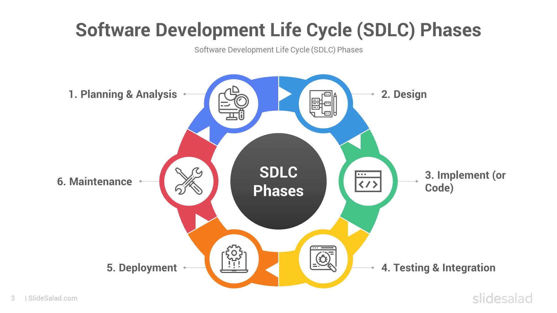
A software process typically includes the following activities:
- Software specification – defining what the system should do
- Software design – planning the system structure and architecture
- Implementation – coding the software
- Validation – testing to ensure correctness
- Evolution – modifying software to meet changing needs
Several software process models are used in development:
- Waterfall Model – a sequential and structured approach
- Iterative Models – allow repeated refinement of the system
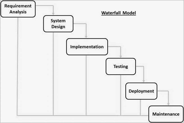
Waterfall Model Diagram
Modern development often follows Agile methodologies, which emphasize:
- Flexibility and adaptability
- Iterative and incremental development
- Continuous customer collaboration
Common Agile frameworks include Scrum and Extreme Programming (XP).

Scrum Process Diagram
Software project management focuses on planning, scheduling, risk management, and coordinating people, processes, and products to ensure successful software delivery.
Software Engineering FAQ - Process Models
1. List the Impact of Software Engineering on Developing Software
Software Engineering (SE) is a disciplined, systematic approach to the design, development, testing, deployment, and maintenance of software systems. It applies engineering principles to software creation, ensuring high-quality, reliable, and efficient outcomes.
Its key impacts on software development include:
- Reduces Complexity: Large software systems are broken down into smaller, manageable modules using techniques like abstraction and decomposition.
- Improves Reliability and Quality: Structured processes minimize defects and ensure the software meets user needs.
- Enhances Maintainability and Scalability: Modular design and documentation allow easy updates and extensions.
- Increases Productivity and Efficiency: Standardized methodologies streamline workflows and promote code reuse.
- Minimizes Costs and Risks: Early planning prevents costly rework.
- Supports Innovation: Enables development of complex systems like AI, IoT, and cloud applications.
- Ensures Timely Delivery: Iterative approaches deliver functional software incrementally.
Impacts of Software Engineering
2. Difference Between Software Engineering and Conventional Engineering
Conventional engineering (civil, mechanical, electrical) deals with physical systems, while Software Engineering focuses on intangible digital products.

Software Engineering: Working with code

Conventional Engineering: Physical structures
| Aspect | Software Engineering | Conventional Engineering |
|---|---|---|
| Product Nature | Intangible (code, algorithms) | Tangible (bridges, machines) |
| Basis | Computer science, logic | Physics, materials science |
| Development Process | Highly iterative, flexible (Agile) | Often linear, rigid |
| Change Management | Easy and low-cost | Expensive and time-consuming |
| Wear and Tear | No physical degradation | Subject to aging, corrosion |
| Maintenance | Code updates, refactoring | Repairs, replacements |
-768.webp)
Key Differences (Inspired by GeeksforGeeks)
Content compiled for educational purposes. Images sourced from public resources.
3. Comment on the Statement: "Software Does Not Wear Out"
4. What problems occur if no life cycle model is followed when developing software?
If no Software Development Life Cycle (SDLC) model is followed, software projects often face severe issues, leading to what is sometimes called the "Chaos Model" or ad-hoc development. Common problems include:
- Lack of structure and planning: No clear phases, resulting in disorganized efforts and missed requirements.
- Over budget and delayed delivery: Costs escalate due to constant rework and scope creep.
- Poor quality: Insufficient testing leads to bugs, security vulnerabilities, and unreliable software.
- Difficulty in maintenance: No documentation or modular design makes future changes hard and error-prone.
- High risk of failure: Many such projects are abandoned or deliver unusable products.
- Team coordination issues: Miscommunication and conflicting work among developers.

The Chaos Cycle illustrating unstructured development
Typical problems without a proper lifecycle model
5. List at least two reasons why the classical Waterfall model can be considered impractical and cannot be used in real projects. Explain how the Spiral model is more practical for real projects.
The classical Waterfall model is linear and sequential, making it impractical in most real-world projects for these reasons:
- Rigid and inflexible: Requirements must be fully known upfront; any changes later are difficult and expensive.
- Late risk discovery: Testing occurs only at the end, so major issues (e.g., design flaws) are found too late to fix cheaply.
- No working software until late: Customers see the product only at the end, increasing the chance of mismatch with needs.

Classical Waterfall Model (Linear and Rigid)
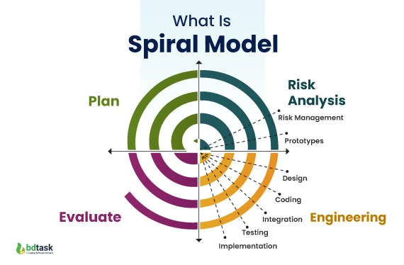
The Spiral model is more practical because it combines iterative development with risk management. Each spiral includes planning, risk analysis, prototyping, and evaluation, allowing:
- Early identification and mitigation of risks.
- Incremental delivery of prototypes for customer feedback.
- Flexibility to accommodate changing requirements.
- Suitable for large, complex, and high-risk projects.
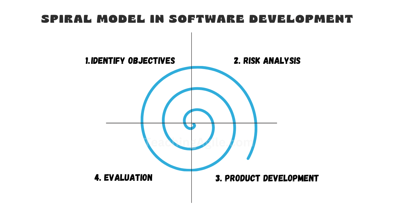
Spiral Model with Iterative Risk-Driven Cycles
Another View of the Spiral Model
6. What do you mean by Agile software development? Comparison between Agile software development and Prototyping model.
Agile software development is a flexible, iterative approach based on the Agile Manifesto (2001). It emphasizes:
- Individuals and interactions over processes and tools.
- Working software over comprehensive documentation.
- Customer collaboration over contract negotiation.
- Responding to change over following a plan.

Agile Manifesto Values and Principles
Comparison with Prototyping Model:
| Aspect | Agile | Prototyping |
|---|---|---|
| Focus | Continuous delivery of working software in short iterations | Building quick prototypes to refine requirements |
| Customer Involvement | High and ongoing throughout the project | High during prototype review phases |
| Scope | Entire project, incremental and iterative | Often used early to clarify requirements before full development |
| Flexibility | Very high; welcomes changing requirements | High for requirements gathering |
| End Product | Production-ready increments | Prototype may be throwaway; final product built separately |

Comparison of Various SDLC Models including Agile and Prototyping

Prototyping Model Flow
7. Explain the major phases used in the Prototyping model of software development.
The Prototyping model builds quick versions (prototypes) to understand and refine requirements. Major phases are:
- Requirements Gathering: Quick collection of basic user needs.
- Quick Design: Preliminary design focusing on visible aspects.
- Build Prototype: Develop a working model (often throwaway).
- User Evaluation: Users review and provide feedback.
- Refine Prototype: Improve based on feedback; repeat until requirements are clear.
- Implement Final System: Engineer the production version using refined requirements.

Major Phases in Prototyping Model
Iterative Prototyping Process
8. Define different types of process models. Explain the process model you would adopt for the services sector and justify your choices with its advantages and disadvantages.
Educational content on Software Engineering process models. Images sourced from public educational resources like GeeksforGeeks and others.
Unit 2: Software Requirements
This unit covers the foundational aspects of gathering, analyzing, and managing software requirements. It includes the Requirement Engineering process, System Modeling techniques, and Software Prototyping as a way to validate requirements early.
Requirement Engineering Process
Requirement Engineering is the systematic process of eliciting, analyzing, documenting, validating, and managing software requirements. It ensures that the software meets stakeholder needs and serves as the bridge between users and developers.
Key activities include:
- Feasibility study
- Requirements elicitation and analysis
- Requirements specification
- Requirements validation
- Requirements management

Requirements Engineering Process (GeeksforGeeks)

Detailed Requirement Engineering Process
System Modeling
System Modeling involves creating abstract representations (models) of the system to visualize, specify, and document its structure, behavior, and requirements. Common techniques use Unified Modeling Language (UML) diagrams, such as class diagrams, use case diagrams, sequence diagrams, etc.
It helps in understanding complex systems, communicating ideas, and guiding design and implementation.
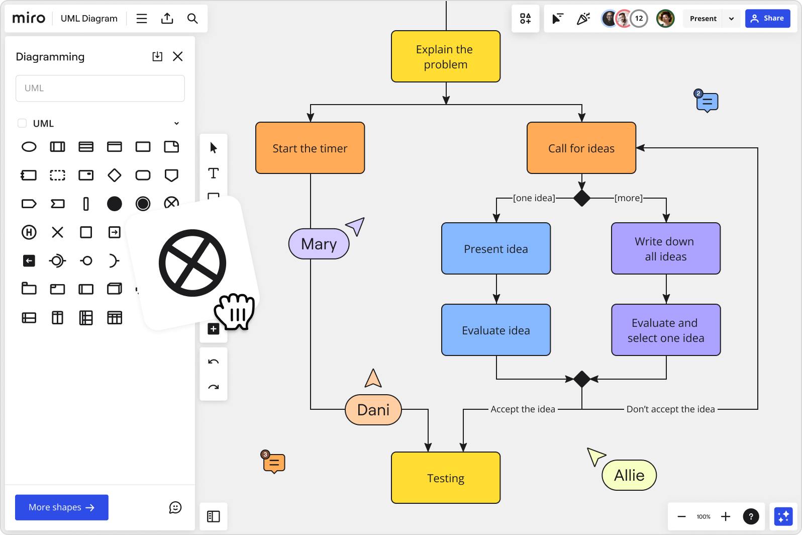
Various UML Diagrams for System Modeling
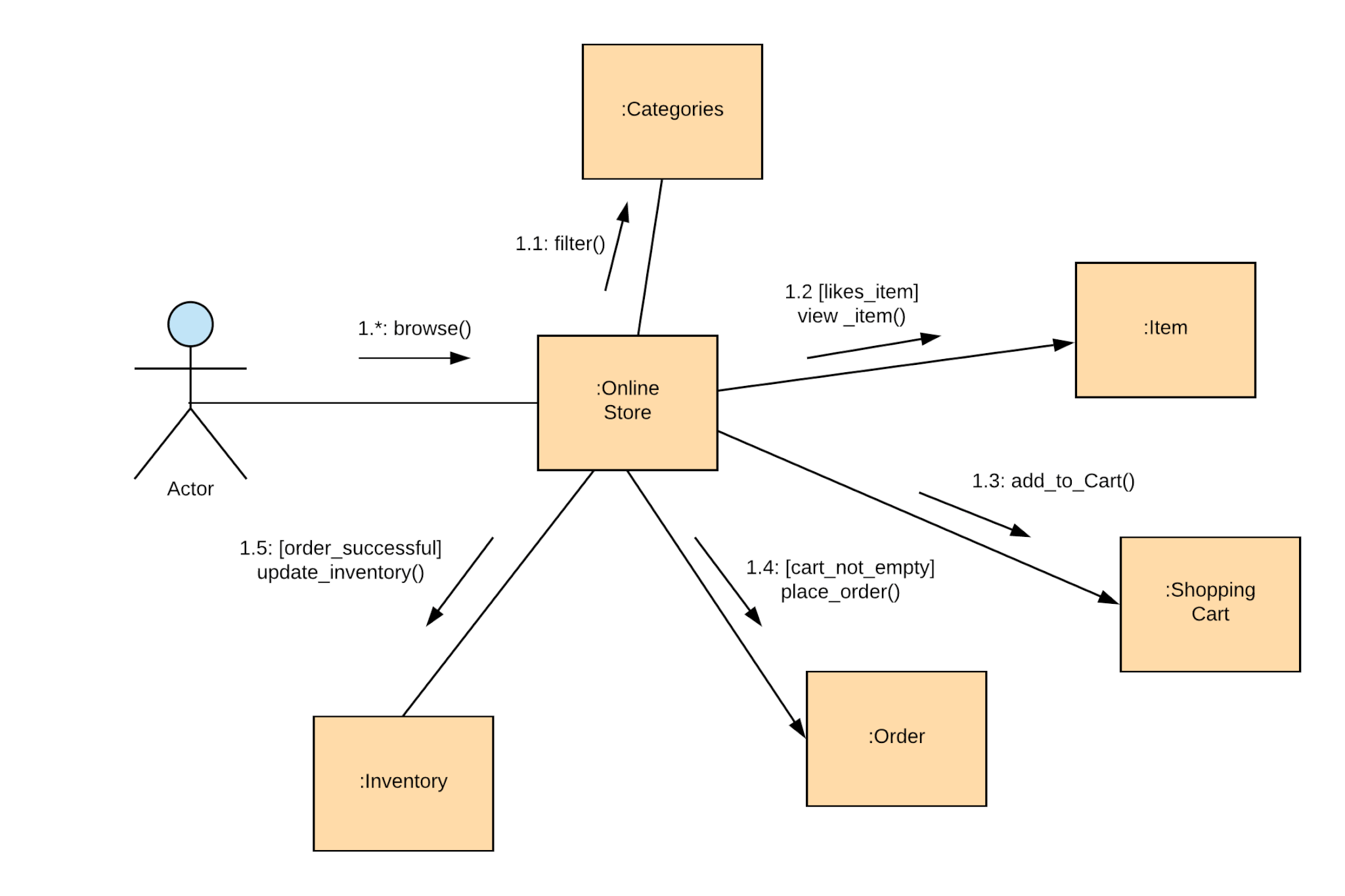
Example of UML Communication Diagram
Software Prototyping
Software Prototyping is an approach where a preliminary version (prototype) of the software is built quickly to visualize and validate requirements. It helps stakeholders understand the system early, identify issues, and refine needs before full development.
Types include throwaway prototypes (discarded after use) and evolutionary prototypes (refined into the final product).
Phases in Software Prototyping Model
Iterative Prototyping Process
Interactive Quiz Section
Test your understanding of Unit 2 with these multiple-choice questions. Click on each question to reveal the correct answer and explanation!
1. Which of the following is NOT a key activity in the Requirements Engineering process?
Options:
- A) Feasibility study
- B) Requirements elicitation
- C) Coding and implementation
- D) Requirements validation
Correct Answer: C) Coding and implementation
Explanation: Requirements Engineering focuses on gathering and managing requirements before development begins. Coding is part of the implementation phase, not requirements engineering.
2. What is the primary purpose of System Modeling using UML diagrams?
Options:
- A) To write the actual code
- B) To visualize and document system structure and behavior
- C) To test the software performance
- D) To deploy the system
Correct Answer: B) To visualize and document system structure and behavior
Explanation: UML models help in understanding, communicating, and designing the system abstractly.
3. In Software Prototyping, what is a "throwaway prototype"?
Options:
- A) A prototype that evolves into the final product
- B) A prototype built quickly and discarded after clarifying requirements
- C) A prototype used only for testing
- D) A high-fidelity prototype with full functionality
Correct Answer: B) A prototype built quickly and discarded after clarifying requirements
Explanation: Throwaway prototypes are used to explore ideas and then thrown away; the final system is built from scratch using refined requirements.
4. Which Requirements Engineering activity involves checking if requirements are complete, consistent, and feasible?
Options:
- A) Elicitation
- B) Specification
- C) Validation
- D) Management
Correct Answer: C) Validation
Explanation: Validation ensures the documented requirements accurately reflect stakeholder needs and are realistic.
Comprehensive FAQ: Software Engineering Key Concepts
Here are 5 important FAQ questions covering major topics from the chapters: Introduction to Software Engineering, Process Models, Software Requirements (Unit 2), and related concepts. Each includes a detailed answer with visuals.
1. Comment on the statement: "Software does not wear out." Explain with a suitable diagram.
The statement "Software does not wear out" means that software, being intangible, does not undergo physical degradation like hardware (e.g., due to friction, corrosion, or fatigue). Hardware follows the classic "bathtub curve" with high infant mortality, stable useful life, and increasing failures due to wear-out.
However, software failure rates often increase over time due to undiscovered defects being revealed during use and errors introduced during maintenance/changes. Thus, while software doesn't "wear out" physically, it can "deteriorate" functionally.
Diagrams illustrating hardware "bathtub curve" vs software failure behavior
2. What is the difference between the Classical Waterfall model and the Agile model? Why is Agile preferred in most modern projects?
The Waterfall model is linear and sequential, with phases completed one after another and little flexibility for changes. Agile is iterative, incremental, and flexible, delivering working software frequently with continuous customer feedback.
Agile is preferred today because requirements often change, risks are managed early, and it leads to higher customer satisfaction and faster delivery in dynamic environments.
Visual comparison and Agile (Scrum) process
3. Explain the Requirements Engineering process with a diagram.
Requirements Engineering is the process of eliciting, analyzing, documenting, validating, and managing user and system requirements. It includes feasibility study, elicitation, specification, validation, and management to ensure the software solves the right problem.
Standard Requirements Engineering Process Diagrams
4. What is System Modeling in software requirements? Give examples of common diagrams used.
System Modeling creates abstract visual representations of the system's structure, behavior, and interactions to better understand and communicate requirements. It uses UML (Unified Modeling Language) diagrams.
Common diagrams: Use Case (actors and functions), Class (objects and relationships), Sequence (interaction over time), Activity (flow), etc.
UML Diagrams commonly used in System Modeling
5. What are the impacts of applying Software Engineering principles in software development?
Software Engineering applies disciplined approaches to development, leading to:
- Reduced complexity through modularization
- Improved reliability and quality via testing
- Better maintainability and scalability
- Increased productivity and lower costs/risks
- Support for innovation and timely delivery
Without it, projects often fail due to chaos, overruns, and poor quality.
Positive Impacts of Structured Software Engineering
6. What is the objective of requirements analysis? Differentiate between functional and non-functional requirements.
Objective of Requirements Analysis
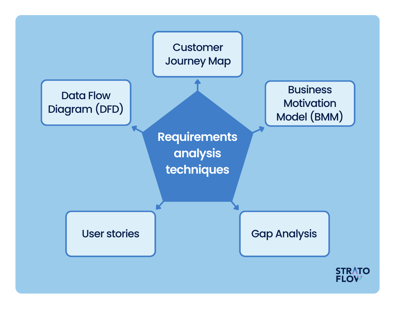
Requirements analysis is a critical activity in the Requirements Engineering process. Its main objectives are:
- To deeply understand and refine the gathered requirements from stakeholders.
- To identify ambiguities, conflicts, inconsistencies, and incompleteness in requirements.
- To prioritize requirements and resolve conflicts.
- To model and document requirements clearly for better communication between stakeholders and developers.
- To ensure the requirements are feasible, testable, and form a solid foundation for system design.
In essence, it bridges the gap between raw user needs and a precise, actionable specification.
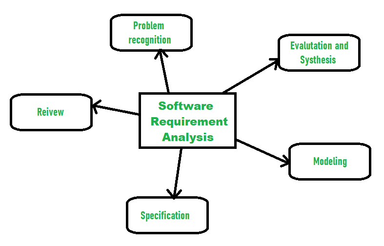
Requirements Management/Analysis Process (GeeksforGeeks)
Detailed View of Requirements Analysis Phase
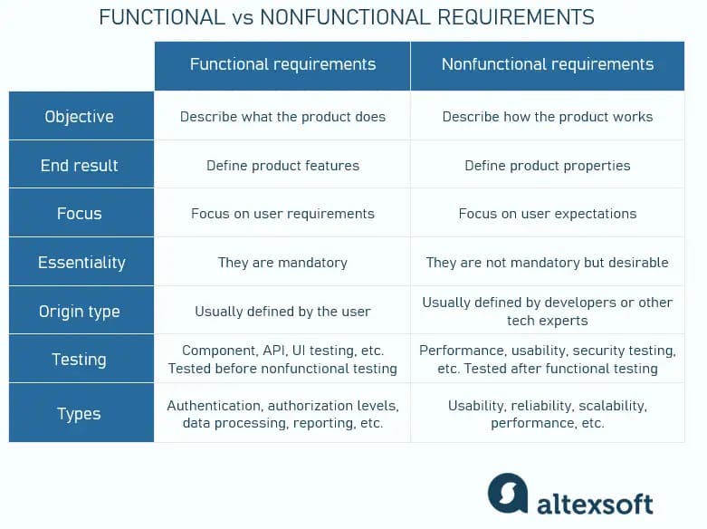
Differentiation Between Functional and Non-Functional Requirements
Functional Requirements describe what the system should do—specific behaviors, features, and operations.
Non-Functional Requirements describe how the system performs—quality attributes, constraints, and performance criteria.
| Aspect | Functional Requirements | Non-Functional Requirements |
|---|---|---|
| Definition | Specify system functions and behaviors | Specify quality attributes and constraints |
| Focus | What the system does | How well the system performs |
| Examples | User login, generate report, process payment | Response time < 2 sec, support 1000 users, 99.9% uptime |
| Testing | Functional/testing black-box | Performance, security, usability testing |
| Mandatory | Usually mandatory | Often critical for success but negotiable |

Comparison Table (Inflectra)
Educational content for Software Engineering Unit 2 with interactive quiz. Images sourced from reliable public resources.
7. What is SRS? List the five desirable characteristics of a good SRS document and explain them.
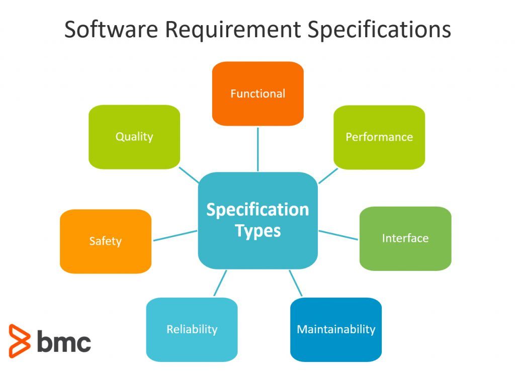
What is SRS?
Software Requirements Specification (SRS) is a comprehensive document that describes the complete behavior of the proposed software system from the user's perspective. It serves as a contract between the client/stakeholders and the development team, detailing what the software will do (functional requirements) and how it will perform (non-functional requirements). The SRS is produced at the end of the requirements analysis phase and acts as the foundation for design, implementation, testing, and maintenance.
A standard SRS typically includes sections like introduction, overall description, specific requirements, and supporting information (e.g., appendices).
Example of SRS Document Structure
Comprehensive SRS Guide Illustration
Five Desirable Characteristics of a Good SRS Document
According to IEEE standards and best practices, a good SRS should exhibit the following key characteristics:
- Correct: Every requirement stated must accurately reflect the system's intended functionality. There should be no errors or misinterpretations of stakeholder needs.
- Unambiguous: Each requirement must have only one possible interpretation. Clear, precise language is used, avoiding vague terms.
- Complete: The document should include all significant requirements (functional, non-functional, interfaces, etc.) and define responses to all possible inputs/scenarios.
- Consistent: No conflicting requirements; terminology and notations are uniform throughout.
- Verifiable: Each requirement should be testable with objective criteria (e.g., measurable metrics instead of subjective terms).
(Commonly, a sixth characteristic "Traceable" is also included, but the above five are core.)

Key Characteristics of a Good SRS

Infographic on Desirable SRS Characteristics
Chapter 3: Software Design
Software Design transforms requirements into a blueprint for constructing the software. This chapter covers key design concepts and approaches at architectural and detailed levels.
Architectural Design
Architectural design establishes the overall structure of the software system, identifying major components (subsystems/modules) and their interactions. It uses styles like layered, client-server, pipe-and-filter, etc., to achieve qualities such as scalability and maintainability.
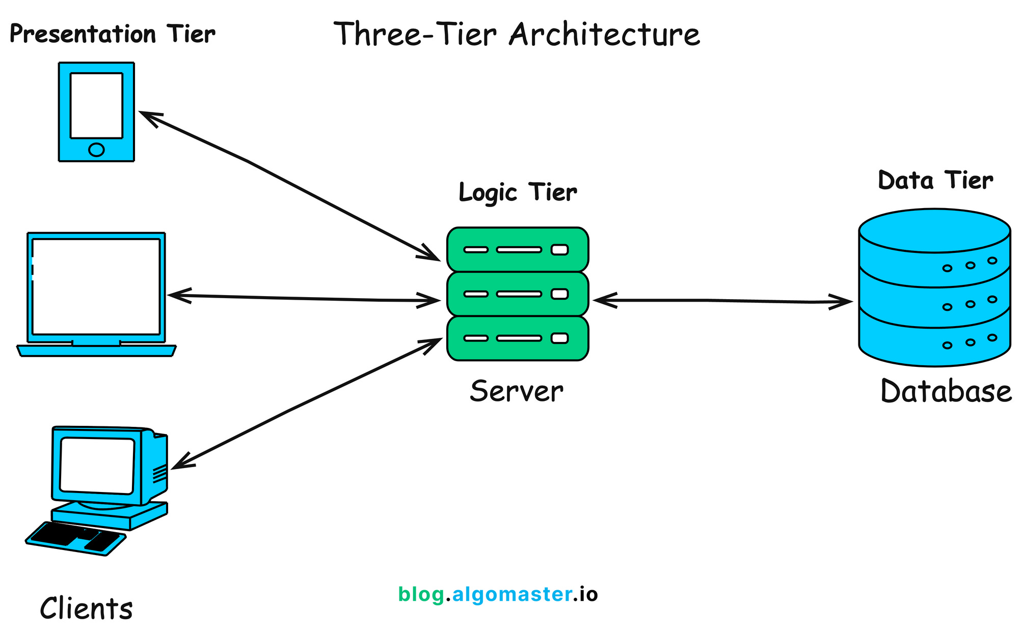
Client-Server Architecture Explained

Layered Architecture (GeeksforGeeks)
Client-Server Architecture (GeeksforGeeks)
Distributed Systems Architectures
Distributed systems architectures spread components across multiple machines/networks for scalability, fault tolerance, and performance. Common patterns include client-server, peer-to-peer, and microservices (service-oriented).

Microservices in Distributed Systems (GeeksforGeeks)
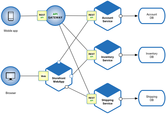
Microservice Architecture Pattern

Microservices Architecture Example
Object-Oriented Design
Object-oriented design (OOD) organizes software around objects (data + behavior) using principles like encapsulation, inheritance, and polymorphism. UML diagrams (class, sequence) are commonly used to model classes and interactions.
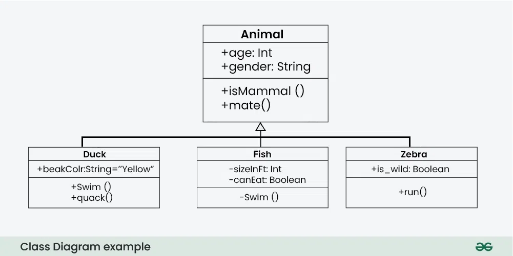
UML Class Diagram (GeeksforGeeks)
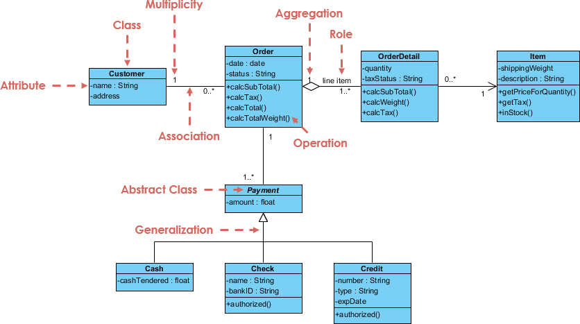
Order System UML Class Diagram

Basic UML Class Diagram Example
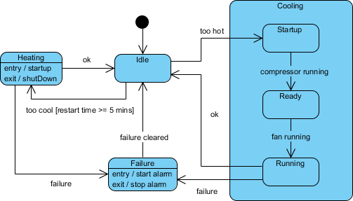
Real-Time Software Design
Real-time software design focuses on systems that must respond within strict time constraints (e.g., embedded systems, control systems). Techniques include state machines, event-driven design, and priority scheduling.

State Diagram Example
Submachine State Diagram

Hotel Reservation State Diagram
Design with Reuse
Design with reuse (or component-based design) involves building systems from existing reusable components/libraries/frameworks to reduce development time, improve quality, and lower costs.

Component-Based Life Cycle Model
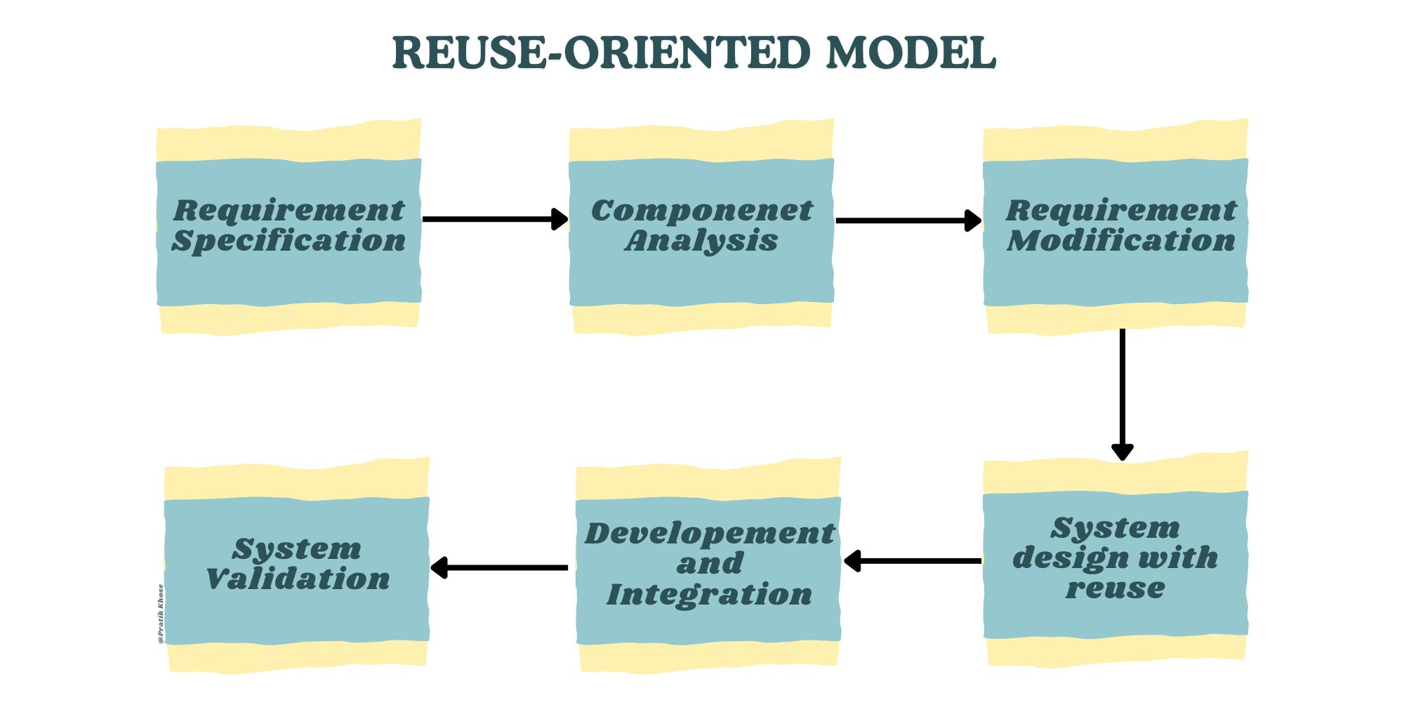
Reuse-Oriented Model
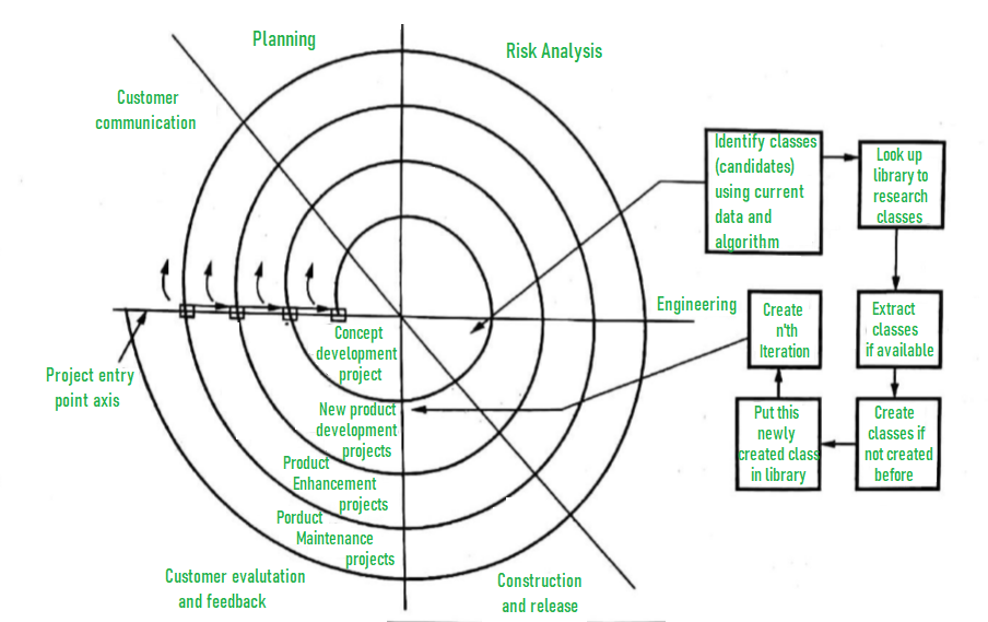
Component-Based Model (GeeksforGeeks)
User Interface Design
User interface (UI) design focuses on creating intuitive, efficient, and aesthetically pleasing interfaces. It involves principles like consistency, feedback, and usability, often using wireframes and prototypes.
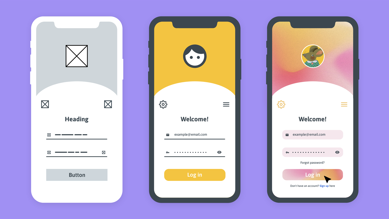
Wireframe vs Mockup vs Prototype
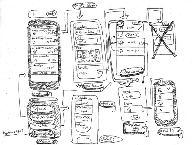
Wireframe and Prototype Concepts
Wireframe Creation Guide
Unit 4: Advanced Software Engineering
This unit explores modern and specialized approaches in software engineering that address complexity, scalability, reuse, and domain-specific challenges.
Software Reuse
Software reuse is the process of building new systems by utilizing existing software assets rather than developing everything from scratch. It aims to reduce development time, costs, improve quality, and increase productivity. Reuse can occur at different levels: code, components, designs, or architectures.
Levels of Software Reuse (GeeksforGeeks)

Success Factors in Software Reuse
Component-Based Software Engineering (CBSE)
Component-Based Software Engineering (CBSE) is an approach where systems are assembled from independent, reusable components that provide well-defined interfaces. Components are developed, acquired, and integrated to form applications, promoting modularity and rapid development.

Component-Based Development Process (GeeksforGeeks)
Life Cycle Model for CBSE
Distributed Software Engineering
Distributed Software Engineering deals with designing, implementing, and managing software systems whose components execute on different networked computers. Key concerns include communication, coordination, scalability, fault tolerance, and security. Modern examples include microservices and cloud-based systems.
Microservices in Distributed Systems (GeeksforGeeks)

Microservices vs Monolith (Martin Fowler)
Embedded Software
Embedded software is specialized computer software designed to control machines and devices that are not typically considered computers (e.g., IoT devices, automotive systems, medical equipment). It must operate under constraints of limited memory, power, real-time requirements, and reliability.

Embedded System Overview (GeeksforGeeks)

Block Diagram of Embedded System

Typical Embedded Software Architecture
Educational content for Software Engineering Unit 4: Advanced Software Engineering.
Unit 5: Verification and Validation
This unit focuses on ensuring that software is built correctly (verification) and meets user needs (validation). It covers planning, reviews, advanced techniques, and testing strategies.
Verification and Validation Planning
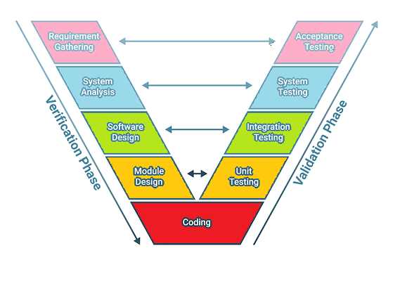
V&V planning involves creating a strategy for verification (are we building the product right?) and validation (are we building the right product?). It includes test plans, schedules, resources, and standards throughout the lifecycle, often illustrated by the V-Model.
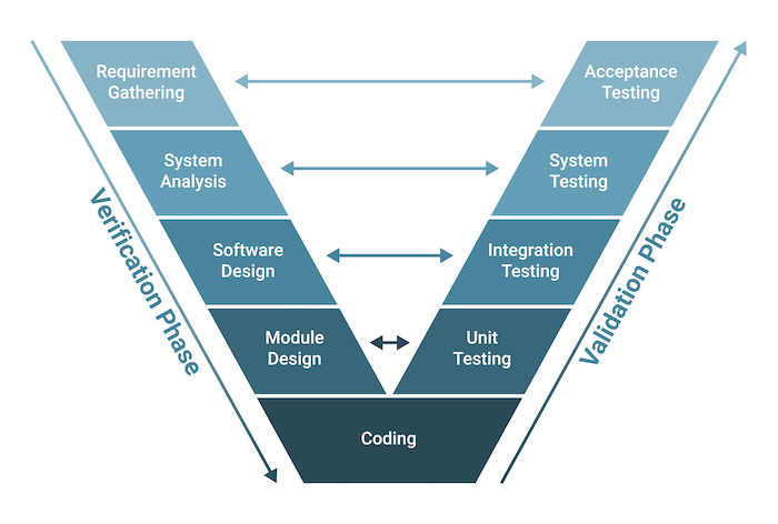
V-Model Showing Verification and Validation Phases
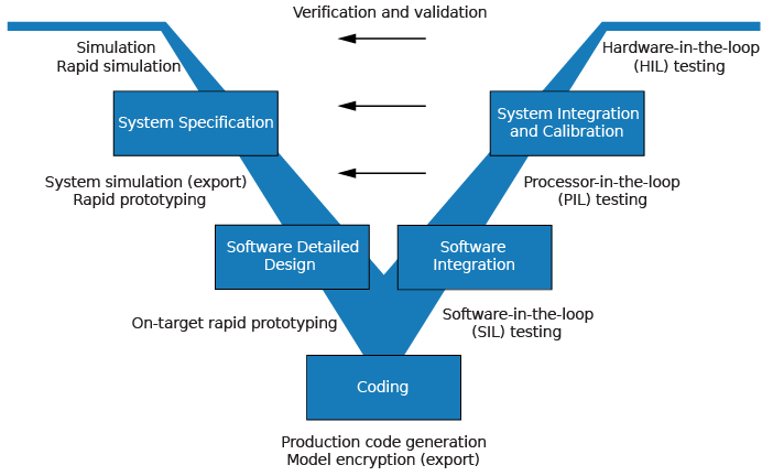
Detailed V-Model
V-Model in Testing Context
Software Inspections
Software inspections (reviews) are static techniques where teams systematically examine code/documents to find defects early. Processes include planning, overview, individual preparation, inspection meeting, rework, and follow-up.
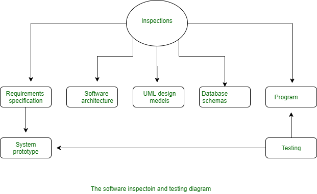
Software Inspection Process (GeeksforGeeks)
Traditional Software Inspection Process
Clean Room Software Development
Cleanroom software engineering combines formal specification, incremental development, statistical testing, and defect prevention to achieve high reliability (near-zero defects).

Cleanroom Development Process

Cleanroom Software Development Overview
Defect Testing
Defect testing (or debugging-oriented testing) aims to discover failures and locate defects. It involves test case design, execution, and defect reporting/management.

Defect Management Process (GeeksforGeeks)
Integration Testing
Integration testing verifies interfaces between components/modules. Approaches include Big Bang, Top-Down, Bottom-Up, and Sandwich/Hybrid.
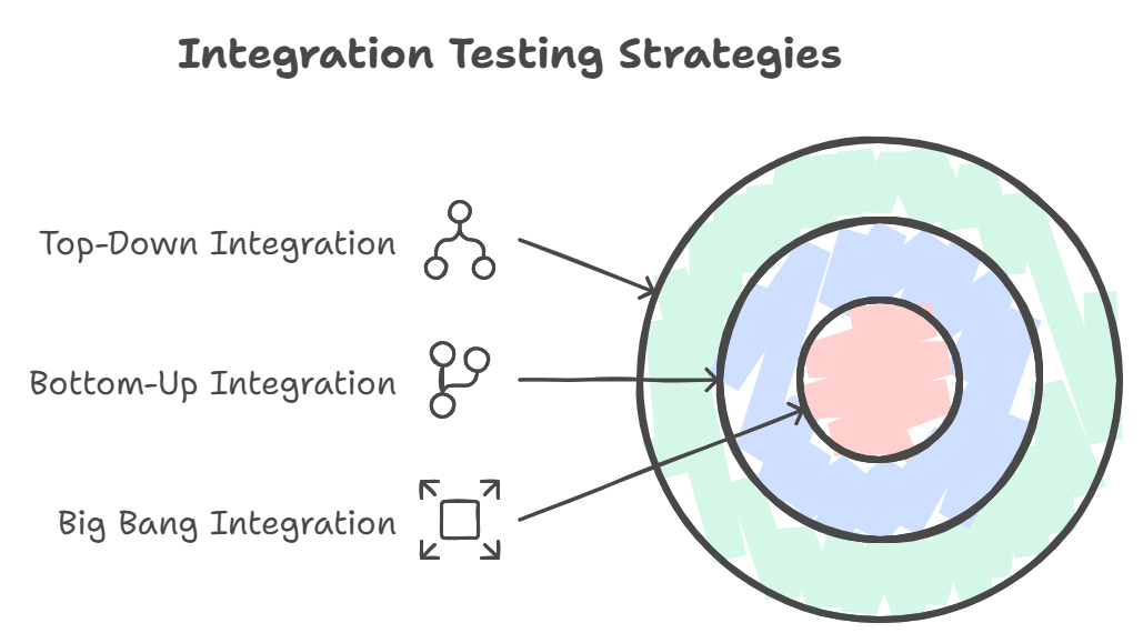
Types of Integration Testing
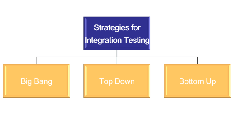
Integration Testing Strategies

Big Bang Integration Example
Object-Oriented Testing
Object-oriented testing focuses on classes, clusters, and system-level interactions, using techniques like class testing, inheritance testing, and scenario-based testing.

FLOOT Method for OO Testing
Testing Workbenches
Testing workbenches are integrated environments/tools supporting the testing process (e.g., test data generation, execution, and reporting).
Example Testing/Reliability Workbench
Critical System Validation
Validation for critical systems (safety, security) involves rigorous techniques like formal verification, reliability modeling, and extensive testing to ensure dependability.

Steps in Critical System Validation
Educational content for Software Engineering Unit 5: Verification and Validation.
Unit 6: Software Quality and Quality Assurance
This unit covers the principles, processes, and techniques for ensuring software quality, including cost estimation, planning, attributes, and safety considerations.
Software Cost Estimation
Software cost estimation predicts the effort, time, and resources required for a project. Techniques include expert judgment, algorithmic models (e.g., COCOMO), and bottom-up estimation to support budgeting and planning.
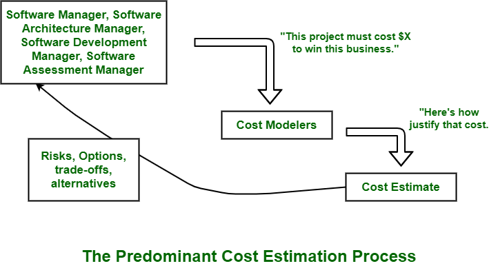
Software Cost Estimation Techniques (GeeksforGeeks)

Various Cost Estimation Techniques
Software Quality Assurance Planning
Quality Assurance Planning defines the strategies, standards, reviews, and audits to prevent defects and ensure quality throughout the development lifecycle.
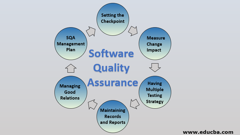
Software Quality Assurance Components (EDUCBA)
-focuses.webp)
Software Quality Assurance Overview (GeeksforGeeks)
Software Quality Assurance Process
The SQA process involves systematic activities like reviews, testing, and process improvement to monitor and enhance quality.

Software Quality Assurance Process Flow
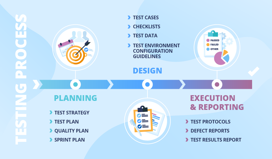
QA Deliverables and Process Timeline
Software Quality Attributes
Software quality attributes (or characteristics) define measurable properties like reliability, usability, and efficiency. Models include ISO/IEC 9126 (older) and ISO/IEC 25010 (current standard).

ISO 25010 Software Quality Model

ISO 9126 Quality Model
Guidelines and Checklists
Guidelines and checklists provide practical tools for reviews, audits, and ensuring adherence to quality standards during development.

QA Checklists Explained

Quality Assurance Checklist Example
Software Safety
Software safety focuses on ensuring software in critical systems does not contribute to hazards, using techniques like hazard analysis, fault trees, and compliance with standards (e.g., IEC 61508).
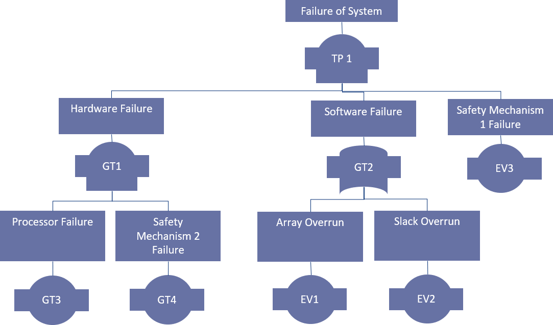
Software Safety Analysis Diagram

Hazard Analysis and Validation Metrics
Educational content for Software Engineering Unit 6: Software Quality and Quality Assurance.
Software Engineering Questions (Exam Preparation)
Question 1 (Unit 6: Software Quality and Quality Assurance) - What do you mean by software reliability and availability? Also state how these project metrics are measured.
Software Reliability: It is the probability that the software will perform its intended functions correctly without failure under stated conditions for a specified period of time. In simple terms, reliability measures how often the software fails (low failure rate = high reliability).
Software Availability: It is the probability that the software system is operational and accessible when required for use at a given point in time. It accounts for both uptime and downtime (including repair/recovery time).
Measurement of These Metrics:
- Reliability Measurement:
- Failure Rate (λ): Number of failures per unit time.
- Mean Time Between Failures (MTBF): Average time between consecutive failures = (Total operational time) / (Number of failures).
- Probability of Failure on Demand (POFOD): Probability that the system will fail when a service request is made.
- Reliability = e^(-λt) (exponential distribution model) where t is operating time. - Availability Measurement:
- Availability (A) = MTBF / (MTBF + MTTR)
where MTTR = Mean Time To Repair (average time to restore after failure).
- Expressed as percentage (e.g., 99.999% = "five nines").

Reliability Metrics in Software Engineering (GeeksforGeeks)

Availability vs Reliability Metrics
Question 2 (Unit 4: Advanced Software Engineering) - Highlight the significance of Software Re-engineering.
Software Re-engineering is the process of examining, analyzing, and restructuring existing legacy software systems to improve maintainability, extend lifespan, and adapt to new requirements without changing core functionality.
Significance of Software Re-engineering:
- Legacy System Modernization: Old systems (often written in outdated languages) become hard to maintain; re-engineering migrates them to modern platforms/technologies.
- Cost Effectiveness: Rewriting from scratch is expensive and risky; re-engineering preserves business logic while reducing long-term maintenance costs.
- Improved Maintainability: Refactoring, modularization, and documentation make future changes easier and less error-prone.
- Enhanced Performance and Scalability: Optimization and restructuring improve efficiency and support new loads.
- Risk Reduction: Gradual transformation minimizes disruption compared to complete replacement.
- Compliance and Security: Updates code to meet new regulatory or security standards.
- Business Continuity: Enables integration with new systems (e.g., cloud, web services).

Software Re-engineering Process (GeeksforGeeks)

Key Activities in Software Re-engineering
Question 3 (Unit 6: Software Quality and Quality Assurance) - What is software project management? Explain how Boehm used COCOMO to estimate effort and time required to develop software based on lines of code.
Question 4 (Unit 3: Software Design) - What is modularity in software design? What are the advantages? Explain how cohesion and coupling are used in modular division of software.
What is Modularity in Software Design?
Modularity refers to dividing a software system into separate, independent modules (or components) where each module performs a well-defined function and interacts with others through defined interfaces. It promotes decomposition to manage complexity.
Advantages of Modularity:
- Improved Maintainability: Changes in one module have minimal impact on others.
- Reusability: Modules can be reused in other projects.
- Easier Development: Parallel development by teams.
- Better Testing: Modules can be tested independently.
- Reduced Complexity: Smaller, focused units are easier to understand.
- Scalability and Flexibility: Easier to replace or upgrade modules.
Effective Modular Design (GeeksforGeeks)

Modularity Fundamentals
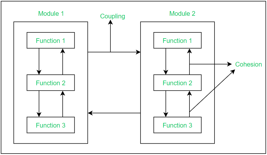
Cohesion and Coupling in Modular Division
Cohesion: Measures how closely the elements (functions, data) within a single module are related. High cohesion (desired) means elements work together for a single, well-defined purpose.
Coupling: Measures the degree of interdependence between modules. Low coupling (desired) means modules are independent with minimal dependencies.
In modular division: Aim for high cohesion (strong internal relationships) and low coupling (loose external connections) to create robust, maintainable modules.

Cohesion vs Coupling Illustration
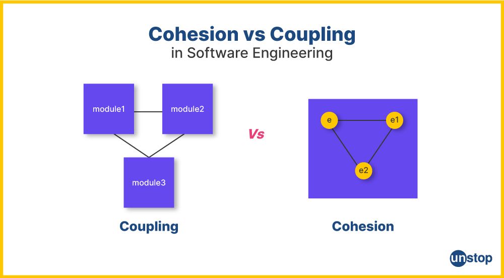
Key Differences Between Cohesion and Coupling
.webp)
Types of Coupling (GeeksforGeeks)
Question 5 (Unit 5: Verification and Validation) - Differentiate between black-box and white-box testing approaches. Which one is preferred more?
| Aspect | Black-Box Testing | White-Box Testing |
|---|---|---|
| Focus | External behavior and functionality (based on requirements/specifications) | Internal structure, code logic, and paths |
| Knowledge Required | No knowledge of internal code | Detailed knowledge of code and implementation |
| Performed By | Testers, end-users, QA team | Developers, unit testers |
| Techniques | Equivalence partitioning, boundary value analysis | Statement coverage, branch coverage, path coverage |
| Level | Higher levels (system, acceptance) | Lower levels (unit, integration) |
Which is Preferred More? Neither is universally preferred; both are essential and complementary. Black-box is often used more in later stages (user-focused) and acceptance testing, while white-box is critical for thorough code coverage. Best practice: Use a combination for comprehensive testing.
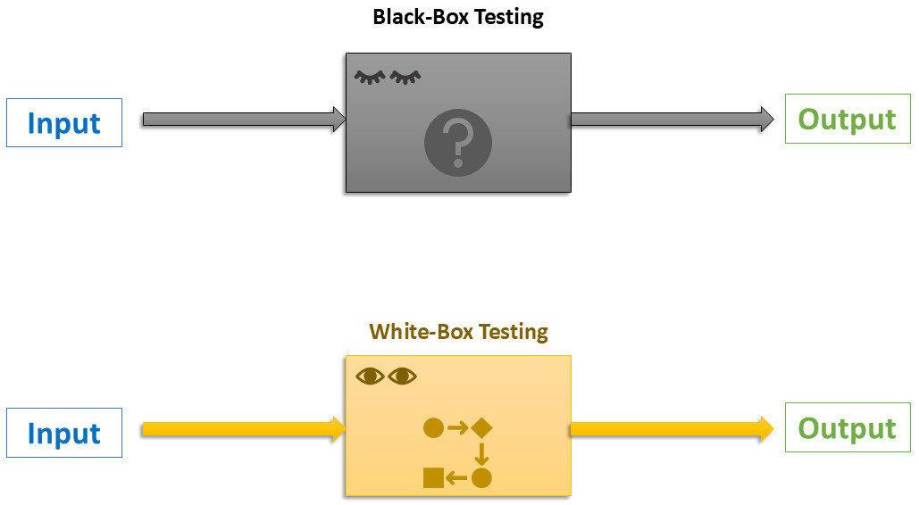
Key Differences Illustration

Black-Box and White-Box Testing Comparison
Question 6 (Unit 4: Advanced Software Engineering) - Describe Distributed Software Engineering
Question 7 (Unit 6: Software Quality and Quality Assurance) - Explain Software Quality Assurance Planning and Software Quality Assurance Process with example.
Software Quality Assurance (SQA) Planning
SQA Planning involves defining the strategies, standards, procedures, resources, and schedules needed to ensure quality throughout the software development lifecycle. It is formally documented in an SQA Plan, which outlines objectives, responsibilities, reviews, audits, tools, and quality metrics.
Example: In a banking application project, the SQA plan may mandate weekly code reviews, adherence to ISO 9001 standards, use of automated testing tools like Selenium, and a defect density target of less than 1 defect per 1000 lines of code.
Software Quality Assurance Process
The SQA process consists of systematic activities to monitor, measure, and improve quality:
- Establish quality standards and procedures.
- Perform reviews and audits (e.g., requirements review, code inspection).
- Conduct testing and defect prevention activities.
- Collect and analyze quality metrics.
- Implement process improvements (e.g., using the PDCA cycle).
Example: In development, the SQA team performs peer reviews on design documents, runs static code analysis tools (e.g., SonarQube), tracks defects using Jira, and conducts retrospectives to refine processes.
SQA Components and Process
SQA Activities Across Lifecycle
Question 8 (Unit 6: Software Quality and Quality Assurance) - Short Notes on (a) Configuration Management
Configuration Management (CM) is a discipline that identifies, controls, tracks, and audits changes to software artifacts (source code, documents, builds) throughout the development lifecycle to maintain consistency, integrity, and traceability.
Key Activities: Version control, change control, build management, release management, status accounting, and auditing.
Common Tools: Git, SVN, Mercurial, Jenkins, Ansible.
Purpose: Prevents chaos from concurrent modifications, ensures reproducible builds, supports rollback, and facilitates compliance auditing.

Configuration Management Activities (GeeksforGeeks)
Question 9 (Unit 4: Advanced Software Engineering) - Short Notes on (b) Software Re-engineering
Software Re-engineering is the process of analyzing and modifying an existing (often legacy) system to reconstitute it in a new form while preserving its external behavior and functionality.
Process Steps: Reverse engineering (understand existing system) → Restructuring (improve code/design) → Forward engineering (implement new version).
Reasons: Enhance maintainability, migrate to modern platforms, improve performance, reduce maintenance costs, and add new features.
Example: Migrating a legacy COBOL mainframe application to a Java-based microservices architecture.
Re-engineering Process Flow
Question 10 (Unit 2: Software Requirements) - Differentiate between Functional and Non-Functional Requirements
| Aspect | Functional Requirements | Non-Functional Requirements |
|---|---|---|
| Definition | Specify what the system should do (features and behaviors) | Specify how the system performs (quality attributes and constraints) |
| Example | "User can log in using username and password" | "Login response time must be less than 2 seconds" |
| Focus | System functionality | Performance, security, usability, reliability, etc. |
| Testing | Functional/black-box testing | Performance, load, security testing |
Examples of Functional and Non-Functional Requirements
Question 11 (Unit 2: Software Requirements) - Mention the main three different types of non-functional requirements which may be placed on a system.
Non-functional requirements can be categorized into three main types:
- Product-oriented NFRs: Concern the qualities of the software product itself.
Examples: Performance, reliability, security, usability, maintainability, portability. - Process-oriented NFRs: Impose constraints on the development process.
Examples: Use of specific tools/languages, adherence to coding standards, time-to-market limits. - External NFRs: Arise from factors external to the system and development process.
Examples: Legal/regulatory compliance, interoperability, environmental constraints (e.g., power usage), scalability in deployment environment.
ISO 25010 Quality Model Categories
Question 12 (Unit 4: Advanced Software Engineering) - What are the advantages of using a distributed approach to systems development?
The major advantages of distributed systems development include:
- Resource Sharing: Efficient utilization of hardware, data, and services across networks.
- Scalability: Easy horizontal scaling by adding more nodes.
- Fault Tolerance & Reliability: No single point of failure; replication ensures continuity.
- Improved Performance: Load balancing and parallel processing reduce response times.
- Geographical Flexibility: Supports global users and distributed teams with local access.
- Heterogeneity: Integration of diverse hardware and software platforms.
Benefits in Microservices Architecture (GeeksforGeeks)
Question 13 (Unit 4: Advanced Software Engineering) - What are the major advantages and disadvantages of decentralized and semi-centralized peer-to-peer architectures?
Decentralized P2P Architecture (Pure P2P – e.g., Gnutella, early BitTorrent)
Advantages:
- High resilience – no single point of failure.
- Excellent scalability – system improves with more peers.
- Low infrastructure cost – no central servers required.
- Better privacy and anonymity.
Disadvantages:
- Inefficient resource discovery (flooding consumes bandwidth).
- Security challenges (hard to prevent malicious nodes).
- Inconsistent availability (peers join/leave frequently).
- Complex routing and management.
Semi-Centralized (Hybrid) P2P Architecture (e.g., Napster, BitTorrent with trackers)
Advantages:
- Efficient search via central directory/index.
- Fast resource discovery compared to pure decentralized.
- Scalable data transfer (direct peer-to-peer).
- Easier administration and monitoring.
Disadvantages:
- Central component is a single point of failure.
- Potential bottleneck under high load.
- Legal and liability issues for central index content.
- Reduced privacy due to central tracking.

Centralized vs Decentralized vs Hybrid P2P (GeeksforGeeks)
Click on each question to reveal detailed answers with explanations, tables, and diagrams.